Home Master Clock LCD Master Clock Kenley Weather
Section Top Intro Design Construction Blynk App Blynk Video Stream Electronics Veroboards Stepper Motor Motor Coupler Schematic Make Project Blynk Widget Code

|
 |
|
This project uses an ESP8266 WIFI board via the Blynk Mobile app to trigger a measure of dry food for your cat or in a suitable outdoor enclosure Koi Carp pellets. Two old mobile phones used as a video servers one monitors the feeding via the Blynk app and another is used as a general IP cam using IP Webcam Pro. The feeder uses the hopper from a cereal feeder and has a stepper motor attached to the feed flaps to rotate them an exact dose of dry food.
Although the hopper can feed 34 measure of food we would only really use this if we were away for the weekend. We also have neighbours/friends and family who could look in on the cat if there are any problems. Our cat has access to the utility room via a cat flap and I use a 2nd old mobile as a monitor to check she is coming and going OK. This mobile runs an app called IP Webcam Pro and it turns your old mobile into an IP cam. |
|
IP Webcam Pro is available from the Google Play store
![]()
Below IP Cam Pro running on an old S4

Once running and port forwarding enabled the video feed can be viewed from the internet.

Make sure your cat has enough water while you are away by using one of these water dispensers.
Design
The feeder is designed to be fitted in a kitchen base unit. Any size down to around 300mm width should be fine.
Using a short length of standard 68mm down pipe cut through the base of the cabinet and a 112.5°
Offset Bend to allow the pipe to exit the cabinet through the plinth and into the cat/dog bowl.
Once the feeder operates gravity will take the feed down the pipe and into the bowl.

Construction
The feeder uses parts from a commercial cereal dispenser.
The dispensers are available as single, double or triples on Ebay.
The cost between the different types is quite low so I went for the triple so I had some spare parts.
If you go for the type shown below they are very easy to modify.

Disassembly of the Cereal Dispenser
To take apart of old dispenser remove the dispensers from the wall mounting brackets.
Then remove the brackets from the wall mont. The brackets are fixed to the plastic wall mounts by two self tapping screws, remove them all.
The brackets can then be re-used in the final project.
Note when fixing the brackets to the new feeder use flat head screws and don't
over tighten or the plastic on the brackets could break away.

Once removed it the bracket carefully fixed to the new wooden mounting frame with flat headed wood screws.

The old hand lever is pulled out of the dispenser with the plastic D shaft.
The plastic D shaft is then pulled out of the hand lever ready to be fixed to the motor coupler.
The plastic handle is not used in this project.


Below single feeder mounted on it's original plastic bracket in a wooden feeder stand.

The feeder sits on a stand made from off cuts of wood. Mouse over the pic below to see dimensions.
These sizes are not that important and can be changed to suit the timber/ cupboard space as required.
All joints are simple screw joints and timer is stained then varnished.
The silver mounting bracket is removed from the mounting board see below.
The power supply and L298N H bridge modules are housed on the left.
The ESP8266 module on the right.

The stepper motor mounting bracket is fixed to a wooden block.

The stepper motor shaft is connected to the feeder drive shaft by a motor shaft coupler.

Once the feeder is constructed the rubber feed flaps will need adjusting so they give a full feed on the set rotation of the stepper motor.
The adjust button on the Blynk app will step the motor a few degrees to ensure the feeder starts in the correct position.
Below setting up the feeder

Above the feeder flaps are not in the correct position to give a full measure of feed.
Using the adjust button moves the flaps a fraction of a turn to ensure a full measure of feed each time.
Below adjusted flaps producing a full measure of feed.

![]()

The Blynk App
Blynk was designed for the Internet of Things. It can control hardware remotely, it can display sensor data, it can store data, visualize it and do many other things.
See the Official "how Blynk Works" page for more details.
The main app page below shows details of each Blynk widget

|
On return from power loss or on restart the Start Date and Time and all count are reset to 0 (the Hopper count returns to 34). The Last Feed Date and Time however do not reset as it is important to know when your pet was last fed.
|
Blynk Video Stream Setup
Setting up the Video Stream on Blynk can be a bit tricky.
| The Blynk help guide says
" Simple widget that allows you to display any
live stream. Widget supports RTSP (RP, SDP), HTTP/S progressive
streaming, HTTP/S live streaming. For more info please follow
official Android documentation. I have tried many different I/P camera but could not get them to work. I have opted to use an old Samsung S3 as a video server using an app called RTSP Camera Server from Google Play.
Once setup I was able to get video and sound onto my Blynk Video Streaming Widget. The settings are crucial as the video will only display if the setting are exactly right. The sound seems to play on most settings. The table below shows the settings that worked on my setup S3 camera server and S7 running Blynk. The encoder setting will probably differ from phone to phone but try h264 if that is an option on your phone.
|
Samsung S3 running as a RTSP server

| RTSP Camera Server Settings | |
| Video | |
| Resolution | 320x240 |
| Frames per Second | 15 |
| Aspect ratio | 4x3 |
| Quality | Medium |
| Encoder | OMX.SEC.AVC.Encoder |
| Capture Method | GLSurface(fast) |
| Overlay info | |
| Battery info | On |
| IP Address | Off |
| Signature | S3 |
| Time Stamp | On |
| Bitrate | 240 Kbits/s |
| Keyframe Interval | 3 sec |
| Audio | |
| Enable microhone | On |
| Stereo | Off |
| Sampling Rate | 8000 |
| RTSP Setup | |
| Enable recording | On |
| RTSP Port | 5560 |
| HTTP Playlist Port | 8094 |
Blynk Video Streaming Settings URL Address rtsp://dyndnshostname.dyndns.org:rtsp port number/camera
To test locally rtsp://camera IP address:8094/camera
Set RTSP and HTTP Playlist Port to suit your network
On your Hub/Router set port forwarding for your camera/phone to the RTSP Port (or HTTP Port if testing locally)
Don't forget to set your Dyndns Host name and Dyndns password in the settings as well.
Clone this project
Log in to the Blynk app and press QR button in Projects gallery.
After scanning the the QR code below a new Project will be created, all the widgets, settings, layout will be cloned.
You will need enough Energy Balance to clone my Project.

Startup
On power up of the feeder all the Blynk app counters, the Hopper indicator bar refills.
The "Start Time and Date" is recorded on the top row of the app.
If you are away and there was a power failure this will update to warn you that the counters and Hopper value may be incorrect.
The "Last Fed Time & Date" do not change.

Feeding from the Blynk App
The animation below shows how the app looks when a feed is made from within the app.
On pressing the feed button there is a short delay while the stepper motor rotates the feeder flaps.
Once the stepper motor stops the ESP8266 module sends a signal back to update the "App Feeds" count ,take a feed off the current Hopper value
and update the "Last Time & Date Fed" . The bar counter drops 1 feed level as well.
Manual Feeding
When a feed is made by pressing the feed button on the ESP8266 module box there is a short delay while the stepper motor rotates the feeder flaps.
Once the stepper motor stops the ESP8266 module sends a signal back to update the "Man Trigger" count ,take a feed off the current Hopper value
and update the "Last Time & Date Fed" . The bar counter drops 1 feed level as well.
Electronics
I have used modules where possible to keep the design and construction of this project as straight forward as possible.
Veroboard is used to mount some of the components/modules there is no PCB layout or design.
I have used a fuse on the main 12v input to this project. The power cable is rated at 2 amp and I have used a 1 amp fuse. I have also fitted a thermal fuse attached
to the stepper motor housing as as additional safety device. The measured current draw with motor running and mobile phones running as IP servers is 250mA.
ESP8266 module
The ESP8266 module contains a CP2102 chip to allow direct programming via Arduino IDE from a Windows PC or Mac.
Specification:
Chip Module: CP2102
Working temperature: -40 ℃ ~ + 125 ℃
Power input: 4.5V ~ 9V (10VMAX), USB-powered
Current: continuous transmission: approx. 70mA (200mA MAX), Standby: <200uA
Size: approx. 45 x 25 x 6mm/1.77 x 0.98 x 0.23''
Weight: approx. 6g

Voltage Regulator Module LM2596
Power for the L298N, ESP8266 module and the Samsung S3 mobile phone is delivered by a LM2596 DC to DC converter.
The 12v feed used by the stepper motor is dropped down to 5volts.
The circuit uses 160mA with the mobile On (display off) and the video server app running.
This rises to 250mA wit the the stepper motor running.

Voltage Regulator Module LM2596
Specifications:
Rectification mode:Non-synchronous rectifier
Module property:Non-isolation buck
Input voltage:4V-40V
Output voltage:1.5V-34V(Adjustable)
Output current:Rated current is 2A,maximum 3A(Additional heatsink is required)
Conversion efficiency:92%( highest )
Switching frequency:65KHz
Output ripple:30mV( maximum )
Voltage regulation:± 2.5%
Load regulation:±0.5%
Dimension:43mmx21mmx14mm(LxWxH)
Motor Drive Controller Board Module L298N Dual H Bridge DC Stepper

|
Specifications L298N as main chip
|
Module and Board Layouts
The modules are housed in Perspex topped boxes
The LN298 H Bridge stepper motor module and DC to DC converter in 1 box.

The ESP8266 module is housed in the 2nd box

2nd box with ESP8266 module removed to show Vero Board layout

Vero Board Layout of Fuse Board

Rear of Fuse Board

Cutaway below shows position of fuse board above stepper motor.

Stepper Motor
This is a short geared NEMA 17 Stepper motor. It has an integrated planetary gearbox with a 26.85:1 gear ratio, the resolution reach 0.067°step angle.
It's a good solution in applications that need very low rotation speeds and/or lots of torque.
I tried an identical motor without the gearbox and it was OK until I added the pet food into the hopper then it jammed.


Make sure the mounting bracket has the inner set of drillings if you use this type of motor with a gearbox.

My Stepper Motor Specs
| Manufacturer Part Number | 17HS13-0404S-PG27 |
| Motor Type | Bipolar Stepper |
| Step Angle(W/O Gearbox) | 1.8° |
| Holding Torque | 3Nm |
| Rated Current/phase | 0.4A |
| Phase Resistance | 30ohms |
| Recommended Voltage | 12-24V |
| Inductance | 34mH±20%(1KHz) |
| Gearbox Type | Planetary |
| Gear Ratio(Exact Gear Ratio) | 26 + 103/121 |
| Efficiency | 81% |
| Backlash at No-load | <=1° |
| Max.Permissible Torque | 3Nm(425oz-in) |
| Moment Permissible Torque | 5Nm(708oz-in) |
| Shaft Maximum Axial Load | 50N |
| Shaft Maximum Radial Load | 100N |
Motor Shaft Coupler
The stepper motor is connected to the feeder d shaft by a motor shaft coupler.
Couplers come is most sizes, my motor has a 6mm shaft and the feeder has a 8mm shaft.
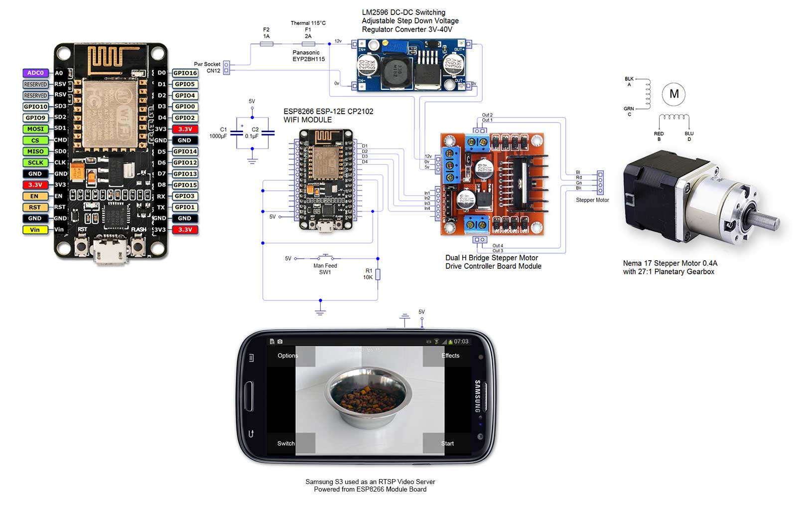
Schematic
Note Thermal fuse F1. This is attached to the stepper motor body above the coils with wire to form a good physical bond.
Note 2. Schematic error Out+ from LM2596 goes to 5v of the stepper motor driver and Out- goes to 0v.
Make this project?
Log in to the Blynk app and press QR button in Projects gallery.
After scanning the the QR code below a new Project will be created, all the widgets, settings, layout will be cloned.
You will need enough Energy Balance to clone my Project.
Example code I have used can be seen in the code section below.
Blynk Widget setting used for this project. See code for further details.
| Pin No | Widget Name | Widget Type | Type 1 | Type 2 | Lables | Pin Type |
| Video Streaming | Video | rtsp://feedname.dyndns.org:rtsp port number/camera | ||||
| Real Time Clock | GMT | |||||
| V0 | Feed Peppa | Button | Push | Feeding/Feed | Virtual | |
| V1 | Hopper Level | Level V | Push | Multi colour | Flip Axis Off | Virtual |
| V2 | Start Time | Value Display | Push | Virtual | ||
| V3 | Start Date | Value Display | Push | Virtual | ||
| V4 | Calibrate | Button | Push | Step/Adjust | Virtual | |
| V5 | Manual Triggers | Value Display | Push | Virtual | ||
| V6 | 1st Feed | Timer | Virtual | |||
| V7 | 2nd Feed | Timer | Virtual | |||
| V8 | Timer Ctrl | Button | Switch | On/Off | Virtual | |
| V9 | Timer Feeds | Value Display | Push | Virtual | ||
| V10 | App Feeds | Value Display | Push | Virtual | ||
| V11 | Last Fed Time | Value Display | Push | Virtual | ||
| V12 | Last Fed Date | Value Display | Push | Virtual | ||
See pic below for pin numbers

Code
I have included the code for this project below and it can be downloaded here Blynk Pet Feeder download
You will need to add your WIFI credentials and Blynk auth token
/**************************************************************
 * Blynk is a platform with iOS and Android apps to control
 * Arduino, Raspberry Pi and the likes over the Internet.
 * You can easily build graphic interfaces for all your
 * projects by simply dragging and dropping widgets.
 *
 *   Downloads, docs, tutorials: http://www.blynk.cc
 *   Blynk community:            http://community.blynk.cc
 *   Social networks:            http://www.fb.com/blynkapp
 *                               http://twitter.com/blynk_app
 *
 * Blynk library is licensed under MIT license
 * This example code is in public domain.
 *
 **************************************************************
 * This example runs directly on ESP8266 chip.
 *
 * Note: This requires ESP8266 support package:
 *   https://github.com/esp8266/Arduino
 *
 * Please be sure to select the right ESP8266 module
 * in the Tools -> Board menu!
 *
 * Change WiFi ssid, pass, and Blynk auth token to run :)
 *
 *
 * Brett
 * v4 Added man switch to test feeding
 * v5 Added motor with gearbox for more torque
 * v6 Turned down int val from 1800 to 900 as it was resetting ESP8266 board
 * v7 Adds feed hopper guage hopper hold 34 feeds
 * v8 added reset to 24 on startup  and clock to show start date and time
 * v9 added calibration button to step a small amout so feed flep is horizontal and
 *  added seperate count for manual activations
 * v10 added correct formating for time
 * v11 added correct formating for date
 * v12 serial prints removed
 * v13 Timers added
 * v14 Add time last feed and removed serial prints
 **************************************************************/

//#define BLYNK_PRINT Serial    // Comment this out to disable prints and save space
#include <ESP8266WiFi.h>
#include <BlynkSimpleEsp8266.h>
#include <WidgetRTC.h>
#include <TimeLib.h>
#include <SimpleTimer.h>

SimpleTimer timer;
WidgetRTC rtc;
//Brett setup stepper
#include <Stepper.h>
// change this to the number of steps on your motor
#define STEPS 400
// create an instance of the stepper class, specifying
// the number of steps of the motor and the pins it's
// attached to
Stepper stepper(STEPS, 5, 4, 0, 2);
int start = 14;
int hopperLevel = 34; // Hopper hold 34 feeds
int val = 900; // steps feed wheel 1/6th of a turn
int calval = 50; // steps to adjust feed flaps to hirizontal position
int manTrigger = 0;
int timerTrigger = 0;
int appTrigger = 0;
int timerEnable = 0;
int isFirstConnect = true;

// Brett end setup stepper

// You should get Auth Token in the Blynk App.
// Go to the Project Settings (nut icon).
char auth[] = "Auth Token";

// Your WiFi credentials.
// Set password to "" for open networks.
char ssid[] = "Your router SSID";
char pass[] = "Your router password";


// Digital clock display of the time and date feeder started
void clockDisplay()
{
if (isFirstConnect == true)
 {
 //Brett store stert time and date feeder started
 // Time
 String displayhour = String(hour(), DEC);
  int hourdigits = displayhour.length();
  if(hourdigits == 1)
  {
    displayhour = "0" + displayhour;
  }
 String displayminute = String(minute(), DEC);
  int minutedigits = displayminute.length();
  if(minutedigits == 1)
  {
    displayminute = "0" + displayminute;
  }

//Date

 String displayday = String(day(), DEC);
  int daydigits = displayday.length();
  if(daydigits == 1)
  {
    displayday = "0" + displayday;
  }
 String displaymonth = String(month(), DEC);
  int monthdigits = displaymonth.length();
  if(monthdigits == 1)
  {
    displaymonth = "0" + displaymonth;
  }


  String startTime = displayhour + ":" + displayminute;
  String startDate = displayday + "/" + displaymonth + "/" + year();

  // Send time to the App
  Blynk.virtualWrite(V2, startTime);
  // Send date to the App
  Blynk.virtualWrite(V3, startDate);


  //Brett end store start time and date
 isFirstConnect = false;

 }
}


void setup()
{
  Serial.begin(9600);
  Blynk.begin(auth, ssid, pass);
 // Begin synchronizing time
  rtc.begin();

  //Brett

  stepper.setSpeed(100); // set the speed of the motor
  pinMode(14, INPUT); // start feeding
  // turns off stepper motor at start
  digitalWrite(5,LOW);
  digitalWrite(4,LOW);
  digitalWrite(0,LOW);
  digitalWrite(2,LOW);
  Blynk.virtualWrite(V1, 34); // sets hopper level to 34 on startup
  Blynk.virtualWrite(V5, manTrigger);// sets man trigger count to 0 on start
  Blynk.virtualWrite(V9, timerTrigger);// sets timerTrigger count to 0 on start
  Blynk.virtualWrite(V10, appTrigger);// sets appTrigger count to 0 on start
  timer.setInterval(100L, clockDisplay);


}

BLYNK_WRITE(V0)
{
  if(param.asInt() == 1) {
    doFeed();
  }
}

 BLYNK_WRITE(V8)// timer enable button
{
  if(param.asInt() == 1) {
    timerEnable = 1;
//     Serial.print("Timer enable: ");
//  Serial.println(param.asInt());
  }
    else
    {
    timerEnable = 0;

   // Serial.print("Timer enable: ");
 // Serial.println(param.asInt());

  }
}

BLYNK_WRITE(V4)
{
  if(param.asInt() == 1) {
    doCalibrate(); // adjust feed flap small steps until horizontal
  }
}

BLYNK_WRITE(V6) //1st Timer Feed
{
  // You'll get HIGH/1 at startTime and LOW/0 at stopTime.
  // this method will be triggered every day
  // until you remove widget or stop project or
  // clean stop/start fields of widget
  //Serial.print("Got a value: ");
 // Serial.println(param.asInt());

  if (param.asInt()== 1 && timerEnable == 1 )// only operate if Timer Ctrl Button is on
  {
  doTimerFeed();
  }

}
BLYNK_WRITE(V7) //2nd Timer Feed
{
  // You'll get HIGH/1 at startTime and LOW/0 at stopTime.
  // this method will be triggered every day
  // until you remove widget or stop project or
  // clean stop/start fields of widget
  //Serial.print("Got a value: ");
 // Serial.println(param.asInt());

  if (param.asInt()== 1 && timerEnable == 1 ) // only operate if Timer Ctrl Button is on
  {
  doTimerFeed();
  }

}


 void doFeed() // rotate feeder 1/6th revolution to release feed
 {
 // turns feed flaps 1/6th turn
  stepper.step(val);
 // turns off stepper motor
   digitalWrite(5,LOW);
  digitalWrite(4,LOW);
  digitalWrite(0,LOW);
  digitalWrite(2,LOW);
  hopperLevel = hopperLevel - 1 ;
   Blynk.virtualWrite(V1, hopperLevel);
   appTrigger = appTrigger + 1 ;// add 1 to appTrigger count
   Blynk.virtualWrite(V10, appTrigger);
   lastFedclock();

 }

void doManFeed() // rotate feeder 1/6th revolution to release feed
// updates hopper level and mantrigger counter
 {
 // turns feed flaps 1/6th turn
  stepper.step(val);
 // turns off stepper motor
   digitalWrite(5,LOW);
  digitalWrite(4,LOW);
  digitalWrite(0,LOW);
  digitalWrite(2,LOW);
  hopperLevel = hopperLevel - 1 ;
   Blynk.virtualWrite(V1, hopperLevel);

  manTrigger = manTrigger + 1 ;
  Blynk.virtualWrite(V5, manTrigger);
  lastFedclock();

 }

void doTimerFeed() // Timer feed rotate feeder 1/6th revolution to release feed
// updates hopper level and timertrigger counter
 {
 // turns feed flaps 1/6th turn
  stepper.step(val);
 // turns off stepper motor
   digitalWrite(5,LOW);
  digitalWrite(4,LOW);
  digitalWrite(0,LOW);
  digitalWrite(2,LOW);
  hopperLevel = hopperLevel - 1 ;
   Blynk.virtualWrite(V1, hopperLevel);

  timerTrigger = timerTrigger + 1 ;
  Blynk.virtualWrite(V9, timerTrigger);
  lastFedclock();

 }


 void doCalibrate()
 {
   // adjust feed flap small steps until horizontal
  stepper.step(calval);
 // turns off stepper motor
   digitalWrite(5,LOW);
  digitalWrite(4,LOW);
  digitalWrite(0,LOW);
  digitalWrite(2,LOW);

 }


 // Digital clock display of the time and date last fed (man app or timer)
void lastFedclock()
{

 //Brett store stert time and date last fed
 // Time
 String fedhour = String(hour(), DEC);
  int hourdigits = fedhour.length();
  if(hourdigits == 1)
  {
    fedhour = "0" + fedhour;
  }
 String fedminute = String(minute(), DEC);
  int minutedigits = fedminute.length();
  if(minutedigits == 1)
  {
    fedminute = "0" + fedminute;
  }

//Date

 String fedday = String(day(), DEC);
  int daydigits = fedday.length();
  if(daydigits == 1)
  {
    fedday = "0" + fedday;
  }
 String fedmonth = String(month(), DEC);
  int monthdigits = fedmonth.length();
  if(monthdigits == 1)
  {
    fedmonth = "0" + fedmonth;
  }


  String fedTime = fedhour + ":" + fedminute;
  String fedDate = fedday + "/" + fedmonth + "/" + year();

  // Send time to the App
  Blynk.virtualWrite(V11, fedTime);
  // Send date to the App
  Blynk.virtualWrite(V12, fedDate);

}

  // End Digital clock display of the time and date last fed (man app or timer)


void loop()
{
  Blynk.run();
  timer.run();

    // get the man switch value
  if (digitalRead(start) == HIGH) // feeds and updates the hopper level/man trigger count on manual trigger
 {

doManFeed();

 }

}