
Section Top Features Ultra HD Video Design Time Keeping Uno Mod Construction 7 Seg Disp PCB Summertime Video Wintertime Video Autotune Video LCD Disp PIR Schematic Main PCB Blutooth Ctrl Panel Leap Sec Leap Sec Video User Manual Flow Charts Code
Design and Construction

Features
Arduino 328 Microprocessor is used to decode and display Time & date from the DCF77 "Atomic" Clock in Mainflingen near Frankfurt Germany
The DCF77 signal is decoded using the fantastic new DCF77 library written by Udo Klein meaning the clock stays in sync and keeps perfect time even with a massive amount of noise on the received DCF77 signal
Udo Klein's DCF77 library continually "Auto Tunes" the quartz crystal so in the rare event the signal can't be decoded the clock remains accurate within 1 sec over many days
The clock provides the following pulses to drive slave clocks 1 sec alternating, 30 sec, 1 min , 1 hour, 24 hr, 15 min chime of quarter hours, hourly chime of hours
Primary display of time in hours, minutes & seconds are displayed on 1" (26mm) green LED 7 segment displays
Secondary 4x20 I2C LCD display is used to display time & date, fast or slow seconds, summer winter correction, display brightness, sync information, signal quality, auto tune'd frequency, auto tuned quartz accuracy and summer winter time mode
The primary and secondary displays are auto dimmed using and LDR and Pulse Width Modulation
The primary and secondary displays are shutdown during daytime and are activated by Passive Infrared detection when the clock detects someone entering the room
Manually triggered automatic Summer/Winter time correction of 30 second slave clocks
Blue-Tooth link for programming, clock pulse status and PIR adjusting
Auto leap second adjustment of 30 second slave and 1 second slave clocks time and date of leap second can be read via Blue-tooth on your PC or Android mobile or tablet
Recording of fast or slow 1 second slave clock pulses on the LCD display as well as time and date stamping of last fast or slow pulse accessible by Blue-Tooth on your PC or Android mobile or tablet

Typical setup with Master connected to home made 12" slave clocks
Below 1 min Ultra HD video showing clock pulsing and chiming 10 o'clock
Design
I designed and built my old Master Clock see photos below in 2004 using a 32.768KHz quartz crystal and logic chips to display the time and derive the pulses to drive all my slave clocks. It also has a DCF77 decoder board that again uses logic chips to decode the DCF77 signal and get a 1 second synchronising pulse to keep the clock on time. The technology used in this clock was actually out of date when I built it as I used the technology I had leant about at college in the late 1970's. I soon found out from comments that no one really used logic chips for this sort of thing anymore and why had I not used a Microprocessor?

Old Logic controlled Master Clock Mk1 showing display board, main board chime board and quartz board. The DCF77 decoder board also logic controlled and is mounted on the rear of the case
After a few years I gave microprocessors a try by building a PIC Microprocessor based Calendar Slave using Oshon Soft Basic , a Meter Clock using Picbasic Pro v3 and a DCF77 Master Bracket Clock using an Arduino 328.
Collection of Master & Slave Clocks built over the last 30 years.

I decided to use Arduino to control my new Master as it seemed tailor made for my basic programming skills as most of the complicated work is done by the people who design and then share the libraries. Arduino is very well supported hardware wise and many complete parts can be purchased ready built as building block for projects.
A MAX7219 drives the primary display, a 4x20 I2C LCD is used for the secondary these help keeping wiring and Arduino 328 pin use to a minimum.
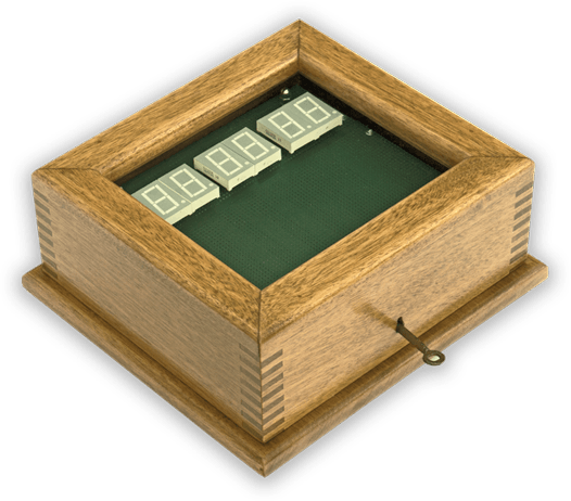
I kept the same type of Oak case used in my old master Clock as it fitted 6 x 1" 7 segment displays perfectly and gave me space to fit in all the other modules.
I have used a PIR module for display shutdown/wakeup with it's own timer and sensitivity adjustment as this uses only 1 pin of the Arduino 328.
A EZ Link Bluetooth Serial Board module enables me to program the clock and read data from it remotely from my desktop PC.

New Master Clock MK2 showing reduced chip/component count and wiring
One of the considerations when building this clock was to reduce the power consumption as the clock is on 24/7. See the table below most of the time the Mk2 clock will draw around 50mA compared to the Mk1's 200mA.
| Power Consumption | |
|
Masterclock Mk1 |
200mA |
|
Masterclock MK2 |
|
| Startup | 35mA |
| Display off during daytime with no movement detected | 40mA |
| Display on 0 brightness | 43mA |
| Display on 2 brightness | 50mA |
| Display on 5 brightness | 62mA |
| Display on 10 brightness | 78mA |
| Display on 15 (max) brightness | 90mA |
Arduino Libraries Used
dcf77.h this Library is the heart of the clock. This outstanding new library written by Udo Klein decodes even a noisy DCF77 signal and auto tunes the quartz crystal.
LedControl.h to drive the LED display and LDC backlight via a
MAX7219 IC.
LiquidCrystal_I2C.h to drive the LCD display
Wire.h to communicate with I2C devices
Time keeping
My old Master Clock was a very good time keeper and as long as I had a good DCF77 signal to keep it in sync it was fine. Every now and then when the DCF77 signal was lost for some time it would gain a second and when correcting it it would then make the 1 second slaves loose a second. This only happened a couple of times a year but re-syncing all my 1 second slaves was a pain.
I have decided to keep using the DCF77 signal from the Atomic Clock in Germany. I could have used the MSF signal from the UK but reception is not good in Surrey as the transmitter has move further North. The DCF77 signal is also better supported as it is used across Europe not just the UK. I will be using the Arduino DCF77 decoder library written by Udo Klein . Udo has been developing this code over the last few years to make it synchronize and lock onto a signal even when there is a massive amount of noise and interference on the signal. While prototyping my new clock I consistently manage to synchronize and maintain a lock even though the DCF77 signal receiver LED that should show a steady 1 second pulse from Germany is flashing multiple times a second.
Udo's DCF77 library code is very very complex but in very basic terms it locks onto the DCF77 frequency using a phased-locked loop and once locked it will actually predict what the DCF77 code should contain and then look for snippets of this code in a very noisy signal. As things like the date do not change that often his code can look for this data in the signal to help it stay locked on! Once in sync with the DCF77 signal it uses it to "auto tune" the backup quartz crystal ensuring if the DCF77 signal is losed the clock still stays in sync.
You can read full details of the development of this library and much more on Udo's site/blog here Blinkenlight.
The only small down side to this library is that it needs an accurate time base on the Arduino to lock into the DCF77 frequency. Modern Arduino boards don't use a quartz crystal ( the one you see on the board is for the serial port) but an inferior 16MHz ceramic resonator. Udo has written a test program to check if your Arduino boards resonator/crystal are up to the job of running his library and can be found here DCF77 Scope . If your board is not up to the job it is very easy to remove the resonator and replace it with a quartz crystal and a couple of capacitors. I have modified my Arduino UNO and it works perfectly with the library.

Modified UNO board


Before

After
Resonator & Resistor removed and a 16MHz crystal with 2 x 22pf capacitors soldered in place of the resonator
The other option is to build your own Arduino as I have done in my LCD Master Clock and on this project. You can get an Arduino chip, holder, crystal and capacitors in a kit for a few £s. If your are using Windows to compile your code you will need an updated compiler see how to do it here (update new versions of the Arduino compiler now work fine). Linux already has this installed but I am not sure about Macs.
Main clock display
I used 1" (26mm) 7 segment display to display time as these have worked perfectly well on my old Master Clock and are legible from a good distance at night and also in daylight. These are driven by a MAX7219 display driver as it can talk directly to the Arduino using a couple of wires and it's multiplexed display simplifies wiring.
Secondary display

4x20 I2C LCD display
|
|
The secondary display as well as showing the time and date will give information on the running of the clock in particular the DCF77 decoding performance. I have used an I2C 4x 20 LCD display for this. Again these displays talk directly to the Arduino over a 3 wire interface and are very good at displaying lots of information close up.
Pulse Monitor
Pulse monitoring uses simple LEDs as they provide a quick visual indication of what pulses are being transmitted by the clock.
Manually Triggered Automatic Summer/Winter time correction of 30 second Slave Clocks
The Master Clock itself auto corrects for summer wintertime changes at 02:00hrs but due to the loud clunk of the 30 second clocks being advanced during summer changes I have added a switch to initialise automatic Summer advance and Winter retard. This is a single non-locking key and the Master Clock will advance or retard the 30 second slaves depending on the current time of year. If it is summertime the clock is advanced 1 hour and winter time the clocks are retarded 1 hour (pulsing stopped for 1 hour as slaves can't go backwards).
In summer time correction mode 120 extra pulses are sent to the 30 sec slave clocks. The LCD display will show "Summer Advance" and will count the 120 extra pulses. When the time is at 00 or 30 seconds the extra pulses are stopped and the 30 sec clocks pulses are sent out as normal. This means whenever the 120 pulses are started the 30 sec slave clocks are only advanced exactly 1 hour.
See demo You Tube video here
In winter time correction mode the clock waits for the next 30 sec pulse before pausing for 120 30 sec pulses. The LCD display will show "Winter Retard" to show 30 sec clocks are being retarded and show the number of missed pulses.
See demo You Tube video here
Construction
My old master Clock had to be completely wired by hand and this took around 4 weeks to complete all the boards. As I can't produce my own PCBs I have used modular construction on my new clock to keep the wiring/vero board construction to a minimum . This also helps with maintenance as I can just swap out a module if it goes faulty.

Master Clock prototyped so I can test the software. The small 7 segment test displays are driven by a MAX7219
and uses the LEDcontrol library by Eberhard Fahle. For testing I used a Arduino Uno with a quartz crytal and capacitors added so it worked with Udo Klein's DCF77 library
Master Clock Construction

The Master Clock case is made of solid Oak. I have stripped back the old dark varnish from this recycled box and re varnished in clear lacquer.
The case is identical to my old master clock but is now a lighter Oak colour.

Display vero board has been spray painted green and comprises 2 parts (7 segment board and LCD/LED board) bolted together and mounted in the case on threaded M5 studding.
In the finished clock the threaded bolts will be covered over with brass tube.
The LED displays are mounted on SIL headers.

LCD Display mounted into a hole cut in the veroboard.

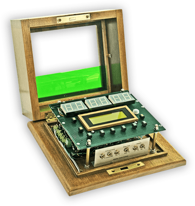
Lid removed to show display board and main board mounting
All 7 segment displays, LCD and LEDs mounted. LDR is on the right of the LCD.
PIR detector is now mounted outside of case as it will not work through the case glass.
Case needs 2nd pane of glass added so displays can be labelled with white Letraset.
Once the 2nd glass panel is in place brass tubing can be cut to length to cover the studding.

Wiring of main board to display board, switch panel, main fuse and EZ link Bluetooth board.

Master Clock construction almost completed. Oak Bezel added to LCD display, brass pillars added over display board studding
and 2nd layer of glass added held in place by brass clips ready for letroset labelling.

Completed Master Clock with letroset labelling applied to the 2nd inner piece of glass.
The 2 glass layers are seperated by a 1mm rubber gasket.

Master Clock and Slaves on test bed ready for testing

7 Segment Display Board


Completed 1" 7 segment display board with MAX2719 board mounted on reverse
The MAX2719 DP driver is connected to the transistor to control the LCD backlight

MAX7219 Board layout
Short video clip showing the almost complete master clock running on my test bench.
As the clock is in day mode the displays can be seen turning off and on as the clocks PIR detects movement.
The 7 segment display has the decimal points activated in software but the Max2719 decimal point output connected to the LCD backlight LED via a transistor to allow the Max2719 to control the brightness of both displays at the same time.
Display now records the Total of Slow 1 Second clock pulses Pulses ( when the master clock corrects forward ) and Fast pulses ( when the master clock corrects back) this resets daily.
As the Udo's DCF77 decoder library is working 100% there are none so far. My other DCF77 LCD Master Clock will show around 8 missed pulses per day. I have decided not to implement pulse correction as Udo's DCF77 library is working so well. I have only added
leap second correction for my 1 second clock pulses.
Summertime Correction including 30 Second Slaves
1 minute video clip showing clock correcting a 30 second slave clock for summertime. Note when the Master is at 30 or 60 seconds pulse counting is stopped to let the slave clock step as normal.
This means 120 pulses will always step the 30 second slaves ahead 1 hour.
The Master Clock itself auto corrects for summer wintertime changes at 02:00hrs but due to the loud clunk of the 30 second clocks being advanced
summer winter changes are initialised by an "Advance/Retard" key the next day. This is a single non-locking key and the Master Clock will advance or retard the 30 second slaves
depending on the current time of year. If it is summertime the clock is advanced 1 hour and winter time the clocks are retarded 1 hour (pulsing stopped for 1 hour as slaves can't go backwards).
Wintertime Correction including 30 Second Slaves
Video Showing Wintertime Correction
30 second clocks can't move backwards so they are retarded by stopping pulses for 1 hour (120 pulses)
On operating the Advance Retard switch the missed pulses are counted from the next 30 second pulse.
Video showing Auto Tune on LCD Display
When the DCF77 signal fails the Master Clock reverts back to Quartz crystal control.
The crystal has a 16MHz frequency and is not very good at keeping time. Udo Klein's DCF77 library now includes "Auto Tune".
The DCF77 signal is used to tune the Quartz crystal frequency over a number of days.
The Auto Tune'd Quartz crystal accuracy and frequency is shown on the bottom of the LCD display.
With auto tune in operation even if the DCF77 signal is absent for long periods of time the clock will stay in sync. This is very important for my slave clock control.
The accuracy of "Auto Tune" is dependant of the temperature of the Arduino 16Mhz quartz crystal and this of course is dependant on the outside and inside temperatures.
I have now managed to get an accuracy of 1Hz but this can vary upto 2Hz.
The LCD Display shows the following information
Row 0
Current time and date should be identical to LED display
Row 1
Clock Name
My Name & software version no
1 second slave clocks total missed (fast) pulses and extra (slow) pulses. When the clock drifts and then resets a second ahead of clock time. An extra 1 second pulse (slow) is required to keep correct time on 1 second clocks. When the clock drifts and then resets a second behind clock time. A 1 second pulse is missed (fast) to keep correct time on 1 second clocks. The total is reset at 06:10 in the morning.
This row also displays the Summer/Winter advance retard information when the clock is correcting the 30 sec slaves
Row 2
7 segment intensity setting. This is controlled by an LDR. 1 is dimmest 15 is brightest setting. This row also displays decoding status Sync'd, Locked, Dirty and Fail
Row 3
This row shows the received signal accuracy in %, the Auto Tuned Quartz crystal frequency accuracy down to 1 Hz and the actual Auto Tuned Quartz crystal tuned frequency in Hz.
Summertime/wintertime indicator GMT/GMT+1
Semi Auto winter Summer correction of 30 second slaves
Summer/winter correction is triggered by a momentary switch with a fail safe "Arm" switch in series.
The single switch will auto advance the 30 seconds clocks an hour in summer and retard them by an hour in winter. The 30 second slaves are advanced by pulsing once per second when the advance/retard switch is operated. This will take 120 additional pulses not including any normal pulses during the advance period.
The clock automatically allows for the normal pulses when advancing by ignoring any normal pulses on 30 and 60 seconds. As 30 second slave clocks cannot be stepped backwards the clocks are retarded by stopping them for an hour on operation of the advance/retard switch. When in retard mode the clock waits for the next 30 second pulse then waits for 120 pulses to pass before starting up again.
The 30 second slave clocks and electro mechanical chimes are driven by monostables and transistors. Pulse length is adjusted by cermet presets on the monostables.
Pyroelectric IR Infrared PIR Motion Sensor Detector Module
I have added an infrared motion detector to the clock. I want to keep the running costs down to a minimum especially as the clock will be running 24/7.
I need the clock on at night so have fitted auto dimming of the 7 segment displays now to 16 levels. I have also connected the decimal point output from the Max7219 to a transistor and the LCD backlight. The transistor then controls the LCD backlight as the 7 segment display is dimmed by the Max7219.
The displays (7 segment and LCD backlight) are now turned off from 08:00hrs to 22:00hrs. The infrared detector will turn them on if motion is detected i.e. you step in front of the clock and they will then turn off after a preset time.
.png)
PIR Module above and modified module below.
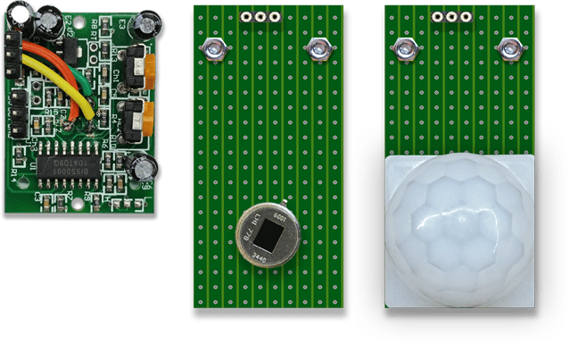
The standard PIR module is modified to work outside of the clock case. The pyroelectric sensor is de-soldered from the module main board.
The main board is fixed inside the clock and the pyroelectric sensor is mounted on an external board facing out from below the clock.
The sensor is then covered over by a circular lens.
Shematic
Master Clock Mk2 Schematic
Note 30second clock and chime driver transistors Q1 to Q3 and components are mounted remote from the clock

Vero Board Layouts
Front Display Board is in two parts and is bolted to a couple of metal strips to hold the boards together.
The top board houses the MAX7219 board attached to the back of the 7 segment display board below.
The lower Vero Board houses the LCD display, LEDs and LDR diffuser.
Both Vero Boards has been spray painted dark green.

The Chromed Dome Nuts attach the boards to the brass studding that is bolted through the back of the Oak case.
Note the white Letroset lettering is on the rear layer of the case glass not the Veroboard.

The front display board behind the oak case and glass.

The MAX7219 IC board below is attached to the back of the 7 segment display board.
Click to see full size image

Click to see full size image

Blue-Tooth Programming & Reading

EZ Link Bluetooth Serial Board
I have added Bluetooth programming via an EZ Link board.
My clock can now be programmed remotely by my PC (will not work with MACs use USB cable & CP2102 module instead) and also monitored remotely by my Android Phone/Tablet
The pair switch mounted on the main switch panel is connected across the Pair switch on the Bluetooth Board (soldered to the 2 resistors see pic above)

Android Bluetooth serial monitor showing Slow and fast 1 second clock pulses with date and time of error pulse ( in this case it shows start-up time), PIR detection, date/time and summer winter offset
The EZ link Bluetooth Serial Board is mounted on the base of the clock.
The 3 LEDs Connection (Or), Receive (Bl) & Transmit (Bl) can be seen through the display vero board holes.

Clock Control Panel

Manual Controls
30 Second Clocks
On - turns On/Off the pulses to the 30 seconds clocks
Advance/Retard - Depending on the clock showing summer or winter time when held down for 1 second steps the 30 second clocks forward 1 hour or retards the clocks 1 hour.
Only works when the Arm switch is set to the Arm position and On/Off switch is On.
Master Clock
Reset - resets the Arduino so the clock will resync
Bluetoth
On - Turns Bluetooth On & Off
Pair - Pairs the clock to a new device
Leap Second Detection and Correction
The clock now detects leap seconds. This is built into the library and the LCD and 7 segment displays auto adjust.
The problem was how to auto correct the 1 seconds clocks. The leap second is added at the end of a minute so instead of the seconds counting to 59
then starting again from 0 the seconds count to 60 and then resets to 0.
The clock looks for the seconds counting to 60 then waits 1 second before starting to pulse the 1 second clock pulse again.
This can be seen on the serial display on my mobile via the EZ-Link Bluetooth board in my clock. I used a test program written by Udo Klein to send dummy leap year data to my clock.
The phone display below shows 0 slow seconds and 1 fast second. The 1st slow second is always there on startup and indicates when the clock was first sync'd up in this case 23:51:44 on the 31/12/14.
These are day totals and are reset at 06:00 am.
The fast second (the seconds are fast compared to DCF77 time) shows the date and time the fast seconds were detected in this case 0:0:0 01/01/15. This is when the leap second was added and the seconds pulsing
was stopped for 1 second to keep in sync with DCF77 time.
This was tested using Udo Klein's DCF77 radio code generator for the Arduino.
see my page here for setup details or Udo's site here. The code makes an Arduino into a low powered DCF77 transmitter so you can send any date and time to any DCF77 clock for testing.

The image below shows the actual output from my clock from the real leap second on the 30/06/15.
The clock displays the fast second as received at 00:59:60 on the 01/07/15 as British Summertime in in operation.
After "Slow Seconds" and "Fast Seconds" on the serial display is the error count per day.
On the image below they show zero as the day count is reset to zero at 06:10hrs every day.
The time and date of the last fast or slow pulse is then recorded on the LCD display.
I have removed the current time and date from the serial out on the latest version of the code.

Short video showing the Master Clock detecting a leap second and stopping the 1 second clock to enable it to stay in sync.
The leap second when detected is time stamped and stored and can be read from the serial port of your PC or Android phone.
It can be seen as "Fast Seconds" (above on my Android mobile) as the 1 second clock had to be paused to stay in sync.

Program Flow Charts
Initial Power Up

Main Program Loop

Continued from main program loop above- Summer Winter Correction and Pulse generation

Arduino Master Clock Mk2 Code v3
V3 now uses Udo Klein's DCF77 library dcf77_xtal available from the Arduino Library Manager tested with v3.3.0
Uses all Atmega328 Pins and nearly all available memory 28406 bytes
Requires the following libraries
LedControl.h
dcf77.h
-Note this clock uses Udo Kleins Release 3 dcf77_xtal
LiquidCrystal_I2C.h
Wire.h
