Section Top Info Credits Animation Telling The Time Control Panel Startup LED Illumination Construction Vero Board Layouts Schematic 3D Parts Decals Code
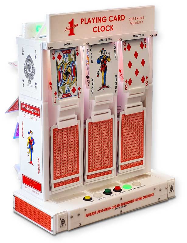
3D PRINTED ESP32 PLAYING CARD CLOCK
Based on a pack of Waddingtons No1 Playing Cards this clock tells the time using individual playing cards.

Using an Espressif ESP32-WROOM-32D module the clock gets the time from an NTP time server and displays the time on three rotating drums.
A DST button sets Summer/Winter Time with a single press.
The clock is backlit at night with WS2812B RGB LED Strips.
3D Printed on a Creality Ender 5 Pro using PLA filament.
Start button added to manually start clock once NTP time is obtained.
Credits
The 3D printed movement of this clock was designed by Shinsaku Hiura
You can download his clock and 3D parts on Thingiverse.
I have adapted his code to run on an ESP32D and added summer winter time correction for use in the UK etc.
Note on Shinsaku Hiura original design the clock steps backwards on power up to set the rotors in their home position so the time is dispalyed correctly when NTP time is obtained.
My clock would not turn backwards reliably so I have removed (commented out) this feature from the code.
Animation showing clock changing from 07:59 to 08:00hrs

How to tell the time
The Joker is 0 and the picture cards are Jack 11 and Queen 12 with the Ace being 1. All other cards are their value.
The Kings are included but never used to display the time.
The hours are displayed on the first rotor from the left and uses all the cards bar the King.
The minutes are displayed on the next 2 rotors the 2nd being Minutes 10s the last rotor displaying Minutes 1s.
As minutes are displayed over 2 rotors only cards 1 to 10 plus the Jokers are ever displayed.
This example shows the time as 10:59

This example shows the time as 12:01

This example shows the time as 4:00

Control Panel
The control panel consist of 3 switches and 3 indicator lights.
Normally just the Green NTP OK indicator will be illuminated.

If the clock is unable to get the time from the NTP server the Red NTP Fail indicator will light.
Pressing Reset will get the clock to try sync again.

On Reset or power up the white GET NTP indicator will flash and the red NTP Fail indicator will illuminate.
Once NTP time is obtained the Red and White indicators turn off and the Green NTP OK light illuminates.

To start the clock the Green Start button is pressed.
The rotors will turn then stop.
Manually set the time on the 3 rotors by rotating them downwards.
Once set the clock will run on it's own.
Daylight Saving time
Pressing the Yellow DST button causes the clock to gain an hour on the next minute.
Releasing the yellow DST button will cause the clock to lose an hour on the next minute.
Starting the Clock
The original clock design will auto set by running the rotors backwards to the end stops.
I can not get the clock to run backwards as there does not seem to be enough power in the stepper motors.
For my version startup is as follows.
Power up the clock.
"NTP FAIL" and "GET NTP" will light with "GET NTP" flashing.
Once time is obtained from the time server "NTP FAIL" and "GET NTP" will go out and "NTP OK" will light.
Briefly press the "START" button.
The rotors will rotate and will then stop.
Manually rotate the rotors to set the correct time.
On the next minute the rotors will automatically rotate to the next minute.
Summer Time
To set summer time press the "DST" button (it will lock).
Summer Time (Daylight Saving Time) will be set automatically on the next minute.
Winter Time
To set winter time release the "DST" button.
Winter time will be set automatically on the next minute.
Backlighting
The clock can be fitted with backlighting if required.
I use 2 strips of WS2812B LEDs with 11 LEDs on each strip.

The strips are fitted to the rear of the title bar at the top of the clock and also to the lower rear of the cards.
The LEDs are controlled with an SP611E remote control module.
The 5v for this module is taken from a separate power module in the rear case.


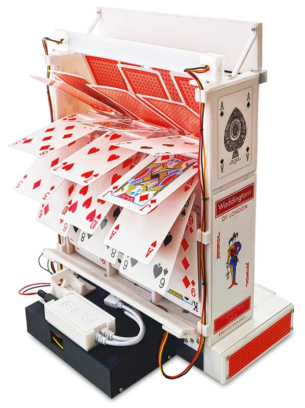
Construction
The circuit uses an Espressif ESP32-WROOM-32D
This is programed using the Arduino IDE.

Not all of the ESP32 GPIO pins can be used.
ESP32 Input Output Pin Availability
| GPIO | Input | Output | Notes |
| 0 | pulled up | OK | outputs PWM signal at boot |
| 1 | TX Pin | OK | debug output at boot |
| 2 | OK | OK | connected to on-board LED |
| 3 | OK | RX Pin | HIGH at boot |
| 4 | OK | OK | |
| 5 | OK | OK | outputs PWM signal at boot |
| 6 | X | X | connected to the integrated SPI flash |
| 7 | X | X | connected to the integrated SPI flash |
| 8 | X | X | connected to the integrated SPI flash |
| 9 | X | X | connected to the integrated SPI flash |
| 10 | X | X | connected to the integrated SPI flash |
| 11 | X | X | connected to the integrated SPI flash |
| 12 | OK | OK | |
| 13 | OK | OK | outputs PWM signal at boot |
| 14 | OK | OK | outputs PWM signal at boot |
| 15 | OK | OK | |
| 16 | OK | OK | |
| 17 | OK | OK | |
| 18 | OK | OK | |
| 19 | OK | OK | |
| 20 | OK | OK | |
| 21 | OK | OK | |
| 22 | OK | OK | |
| 23 | OK | OK | |
| 24 | OK | OK | |
| 25 | OK | OK | |
| 26 | OK | OK | |
| 27 | OK | OK | |
| 28 | OK | OK | |
| 29 | OK | OK | |
| 30 | OK | OK | |
| 31 | OK | OK | |
| 32 | OK | OK | |
| 33 | OK | OK | |
| 34 | OK | X | input only |
| 35 | OK | X | input only |
| 36 | OK | X | input only |
| 37 | OK | X | input only |
| 38 | OK | X | input only |
| 39 | OK | X | input only |
Stepper Motor & Driver

The 28-BYJ48 Stepper Motors are one of the most commonly used stepper motors.
The motor has a 4 coil unipolar arrangement and each coil is rated for +5V.
|
No: |
Pin Name |
Wire Color |
Description |
|
1 |
Coil 1 |
Orange |
This Motor has a total of four coils. One end of all the coils are connect to +5V (red) wire and the other end of each coil is pulled out as wire colors Orange, Pink, Yellow and Blue respectively |
|
2 |
Coil 2 |
Pink |
|
|
3 |
Coil 3 |
Yellow |
|
|
4 |
Coil 4 |
Blue |
|
|
5 |
+5V |
Red |
Supply +5V to this wire, this voltage will appear across the coil that is grounded. |
Dimensions

ULN2003 Stepper Motor Driver
The ULN2003 stepper motor driver PCB provides a direct drive interface between
your microcontroller
and stepper motor. The PCB provides 4 inputs for
connection to your microcontroller, power supply
connection for the stepper
motor voltage, and ON/OFF jumper, a direct connect stepper motor header
and 4
LEDs to indicate stepping state.

ULN2003 Module Schematic

Connecting the 28BYJ48 to the ULN2003

Cases
There are 2 cases fixed together with M3 nuts & bolts.
The larger case holds the stepper motor drivers and supports the main clock frame and the smaller rear case houses the ESP32D on a Vero board.

The top of the lower case contains the control panel & indicator LEDs.
There are 3 slots with diffusers to allow the stepper motor driver board LEDs to shine through.

Full assembly details can be found in the original video of this clock
Shinsaku Hiura original clock video
Start by fixing the hinges to the rotor.
Note the hinges should be fitted this way up when looking at the front of the rotor.
The curve adds a bend to the card making it stiffer.

The picture below shows the orientation of a card fixed in the rotor & viewed from the front.

The hinge arms will need to be bent outwards to clip them on the rotor.
The hinges tend to snap at base of the hinge pivot arms.
I found some gentle heat with a de- soldering hot air gun or nozzle of a glue gun made the arms temporarily pliable to prevent any breakages.
Once clicked in place ensure full movement of the hinge by squeezing the pivot point between the fingers and rotating.

Once all the hinges are fixed to the rotors fix the rotors to the axis.
I used super glue to fix the rotor in place.
Make sure the rotor is fixed square to the axis, there should be an even gap around the rotor and the circular drum on the axis body.
This will ensure the rotor does not wobble when rotating causing cards to rub on the axis frame.
There is not a lot of spare torque in the 28BYJ48 stepper motor and any rubbing will cause it to loose steps and will eventually make the cards dog-eared.


Veroboard Layouts
Modules removed

Modules in place

Rear of Veroboard

Schematic
Note ESP32D PSU set to 5v preferably but may need setting higher if 5v stepper motors fail to turn correctly.
This voltage is also fed to the ESP32D regulator so the voltage should be get as low as possible.
Click to show large version in a new window

3D Printed Parts
Parts included with original download from Thingiverse
Axis
This provides a fixing point for the stepper motor and rotor

Rotor
Fixed to the axis with a bit of super glue the rotor provides pivot points for the hinges.

Hinges
Hinges are clipped onto the rotor pivots.
I found that a bit of gentle heat with a miniature hot air gun or nozzle of hot melt glue gum to the base of the pivot arms made clipping the hinges onto the rotor pivots easier.
Base
The 3 completed axis and stepper motor drivers are mounted on the base.

My version uses the original base with the stepper motor plate cut off.

The clock contains 3 of these axis & rotor modules 2 for minutes and 1 for the hours.
Extra 3D Printed Parts for my Version
Download my 3D parts by clicking the icon below or download from Thingiverse

Part Location

BracketLeft 2 off
Fixes to the main axis with M2 self tappers to make the structure more rigid. Also fixes to the top bracket above with M3 nuts & bolts.
This is duplicator for the right hand side of the clock.

BracketLeftCover 2 off
Slides into the bracket above with a friction fit.
Decals can be fitted to this panel if required.
This is duplicator for the right hand side of the clock.

braketLeftRightTop 2 off
Fixed to the bracket above with M3 nuts & bolts and also to the top bar via top bar brackets.
This is mirrored in my slicer for left and right versions.

BracketLeftRightTopCover 2 off
Friction fitted into the top bracket above.
This is mirrored in my slicer for left and right versions.
Decals can be fitted if required.


CableClipLED 8 off
Holds the 3 wires for the LED strips down the rear of the clock.

DiffusserStandTop 3 off
Diffuses the light from the LEDs off the stepper driver boards.

ESP30CoverTop
Top cover for the main ESP32 control Veroboard

ESP30CoverBase
The main ESP32 control Veroboard is fixed with M2 self tappers to this base.

FootFront 3 off
Front foot to be fixed to the stand base

FootRear 2 off
Rear foot fixed to the rear of the stand base and ESP32 cover base above

FrontBar

LEDCover10mmLED 3 off
LED cover/diffuser for 10mm LEDs on the standtop

LEDStripBracket 2 off
Holds the lower rear LED strip to the clock frame with M2 self tappers.
Mirrored in my splicer left & right

LEDStripBracketRear
Holds the upper LED strip to the clock frame with M2 self tappers.

Playingcard 2 off
Decorative panel glued to stands left and right.
Decal added.

sidepanelcover 2 off
Decorative side panels fixed to the stands left & right with M2 self tappers.
Decal added.

Spacerbase 2 off
Fixed with M3 bolts spaces the stand and ESP32 bases apart.
![]()
Standbase
The stand base holds the 3 stepper motor driver boards with self tappers.
M3 bolts with spacers fix it to the ESP32 base.

Standleft
As the frame of this clock is larger than my printer can handle this is an extensions to the main stand to support the clock frame above.

StandRight
As the frame of this clock is larger than my printer can handle this is an extensions to the main stand to support the clock frame above.
The right stand has an extra cutout for the Mins 1s stepper motor wiring.

StandTop
Provides a cover for the driver boards and stand for the clock frame.
Has cutouts for LEDs, swiches and driver LED diffusers.
Decal fixed for switches/LEDs lables.

Title
Title bar for the clock with Decal affixed.
The bottom of the title has a rebate to fit onto the top bar.

TitleBracket
Supports the Title bar above with M2 self tappers to the clock frame.

TopBar
Ties the 3 axis modules together to make the structure rigid.
Fixed with M2 nuts & bolts to holes drilled in the top of the axis card stop.
Also fixed at both ends via spacer brackets to the top side brackets.
The holes are slotted to allow vertical adjustment to the axis modules.
Decals for Hours and minutes rotors added.


TopBarBracket
Ties the top bar to the left top bracket.

TopBarBracketRight
Ties the top bar to the right top bracket.

LEDCtrlHolder
Holds the control module or the LED strips in place with M2 self tappers.
Fixed to the top of the ESP32 cover with M2 self tappers.

Decals
Decals are printed on Inkjet transfer paper.
I use Inkjet Transfer paper from BigBite Studio.
You can see details from my Word Clock site here
I use a low cost Airbrush (Fenga BD183) to apply my Inkjet Transfers.

I use an 0.8mm jet to apply acrylic paint.
This is an example panel from my Automatic Watch Winder page.
Prepare the control panel by rubbing flat/filling to give a good flat surface for the inkjet transfer.
A good thick coat of primer/white paint helps in getting a nice flat surface.
Once printed on Inkjet Transfer paper I let the Ink dry in a warm room.
I spray lots of thin coats of clear Acrylic varnish to the Inkjet Transfer paper to build up a good thick coat.
If the varnish is applied to quickly the Ink will tend to bleed into the Inkjet paper.
The varnished Inkjet Transfer paper is then left to dry.
Once fully dry the paper is then soaked in water.

The inkjet transfer is slid off the backing paper onto the white control panel.

The printed crosshairs are used to align the transfer over the potentiometer holes.
Any air bubbles are removed and the transfer is left to dry before some final coats of clear varnish to protect it.
Once the Varnish is dry cut the clear inkjet transfer film from around the holes in the control panel.
A final quick coat to varnish will seal the cut edges around the holes.

Decals
Title Decal

Side Decal

Ace of Spades Decal for both sides

Waddingtons Joker Decal for both sides

Hours & Minute Decals for top bar

Download zip for all above files
Download Decals
Code
Note before using the code your router SSID & Password and your local NTP Server details need to be added.
CardClock10_Web download