
Section Top Standard Printer Modified Printer Enclosue Enclosure Plans Spool Holder 3D LOGO Printer Addons Octoprint Octoprint Power Mon Octoprint Enclosure Fire Shutdown Filament Scale Temperature Mon Panel Enclosure Thermostats
3D PRINTER PROJECTS
Creality Ender 5 Pro with DIY Enclosure built onto IKEA Alex drawers
This is a huge project & the site is very much a work in progress contact me via my guestbook for any info not uploaded yet
Projects
"IKEA Alex" based Ender 5 Pro Enclosure
Fire Shutdown
Filament Roller
Filament Scale
Enclosure Temperature Monitor
Enclosure Heater & Controller
OctoPi voltage monitor
OctoPi Printer control panels
Printer Bed Lights
Creality Ender 5 Pro Standard Build

The Ender 5 Pro comes in a kit of 8 parts

Creality Ender 5 Pro Modified Build

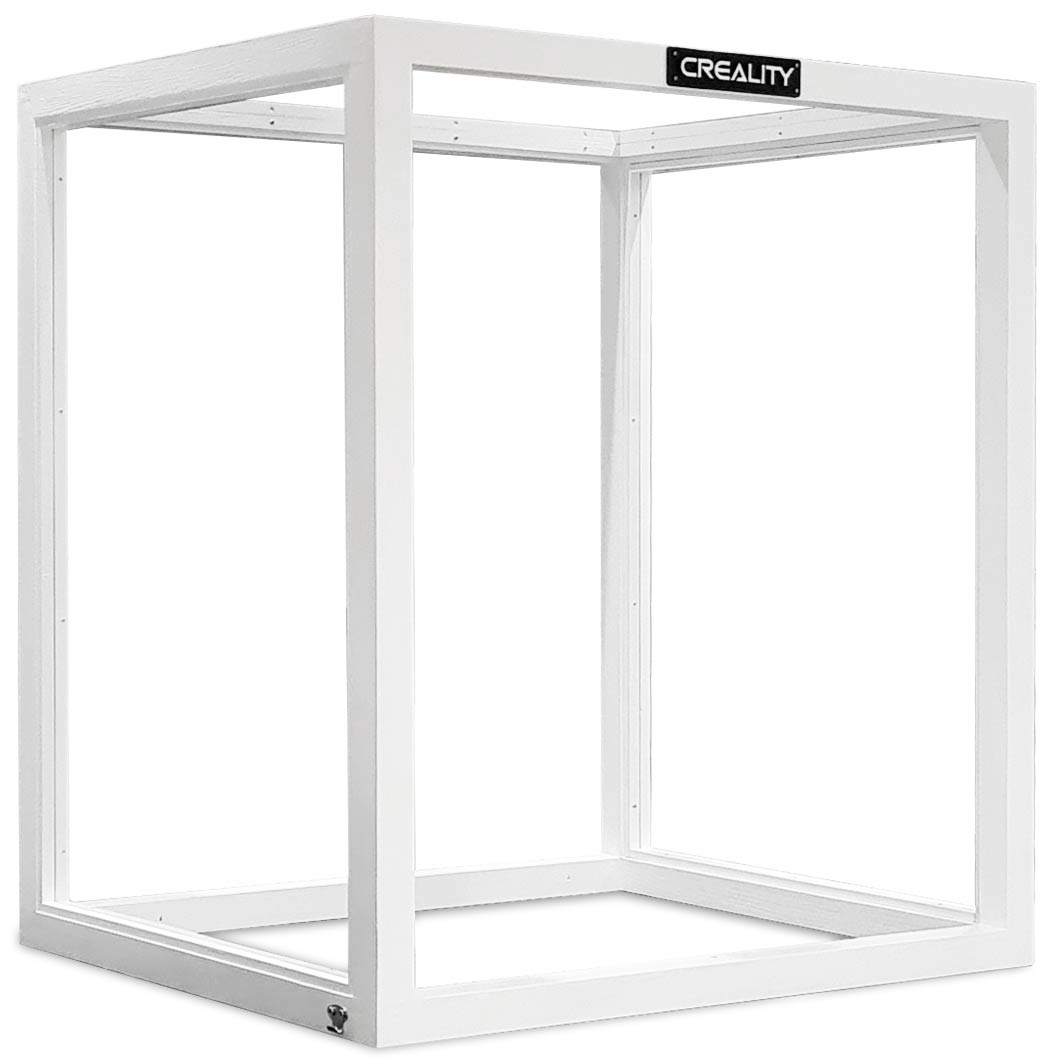
Enclosure Construction
Designed for a Creality Ender 5 Pro but will work with any printer of a similar size..
The enclosure is built onto an IKEA Alex chest of drawers and is designed to be positioned against a wall.
My unit is on an external wall and is vented outside using a 4" bathroom extractor fan.
The whole unit can be pulled out for maintenance as the Alex drawers have large castors.
The enclosure is constructed from 32mm square section timber painted white and overlaps the Ikea Alex drawers by 70mm at the back.
This is for ventalation of the cabinet.
12mm x 8mm glass bead holds the Perspex sheets in place.
The beading is nails and filled on the outside bead and screwed on the inside so the Perspex can be changed out if required.
20mm x 12mm timber beads are used as door stops for the 2 Perspex doors.
5mm Perspex is used for the front doors, 3mm for the sides and 4mm for the top.
Self closing hinges hold the doors shut against the dust seals.
The enclosure cuts down printer/fan noise from 58dB to 44dB measure at 1M.

Enclosure showing the ventilation overlap at the rear of the IKEA Alex drawer cabinet

Creality Ender 5 Pro Enclosure Top No Doors fitted
The IKEA quoted dimensions in mm are W670xD480xH660
My cabinet is W667xD480xH665 so best to check the dimesions especially the width before constructing the enclosure.
I built my enclosure 665mm wide so there the base is 1mm wider both sides.

Exploded view of the enclosure frame.
The top and bottom sections are screwed and glued first then the four uprights are also screwed and glued together.
Note the lower rear section is screwed only as it is removed later.
The lower rear section of timber is removed once construction is complete to allow the enclosure to be slid off the drawer stand.

Front view of the enclosure showing wall mounted extractor fan used to vent the cabinet.
Cool air is drawn up from the lower rear of the enclosure.

Rear view showing dust seal on the rear timbers

Releasing the four catches allows the Enclosure to be slid off for easy access to the 3D printer

Enclosure details
The enclosure is "glazed" in Perspex sheet and to cut down on cost I have used different thicknesses depending on the location.
The 2 sides use 3mm Perspex as this is thick enough to give some rigidity.
The top uses 4mm Perspex to prevent it sagging under it's own weight.
The front doors use 5mm Perspex to give rigidity to the frameless doors.
Once the enclosure frame had been built I measured the exact dimensions (-5mm) and ordered Perspex sheet using an online company who cut Perspex sheet to size.
The front doors were ordered with a polished edge as they are a frameless design.

The Perspex enclosure doors are fitted with self closing hinges to hold them shut against the dust seals.
On the completed enclosure the timber brace at the rear is removed.

Door Knob
The door knobs are mounted direct to the Perspex with a metal washer on the screw side and a printed plastic washer on the knob side.

Hinge Mounting
Front of hinge showing front bolt washers and front hinge washer

Hinge Washers Front & Rear
The rear mounting surface of the hinges has a raised area that will damage the Perspex sheet even with a flat washer over it.
I have added a cutout to the rear washer to accommodate the raised area.

Make sure the rear hinge washers with the cutout are fitted on the rear of the hinge as shown.

Hinge opened to show rear bolt washer and hinge between front and back washers.
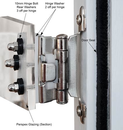
The Perspex door are mounted on 2 pairs of Self Closing Cabinet Door Hinges


3D Printed washers and spacers to protect the Perspex click to download 3D Printer files
Front Hinge Support
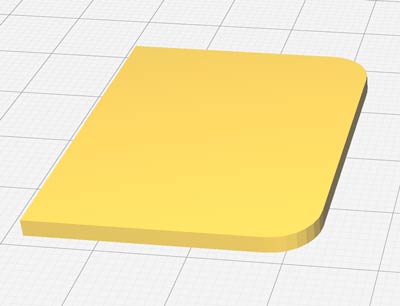
Rear Hinge Support with cutout

17mm washer for door knobs

10mm washer for hinge bolts

The enclosure is fixed to the stand using 4 pairs of Stainless Spring Loaded Toggle Clips

Enclosure Plans
All joints are glued and screwed except the lower rear brace that is screwed only so it can be removed after construction.
Click for full size image

Frame Sections
Front Frame Section

Frame Sections (bar front)

When testing out the enclosure build using the IKEA Alex base I found the width of the base made access to the filament reel awkward.
As the height of the enclosure was not set by the dimensions of the Alex drawers I increased the enclosure height to allow for the filament reel to be mounted on top of the printer.
I modified the printer by moving the extruder and modified reel roller to the rear top rail.
The filament tubing was cut down to fit.
Modified Spool Reel
I have used 3 different parts to make this Spool Reel
Filament Spool Roller by mistertech

Creality
(Ender 3) Filament holder 80mm spools by mjoaris
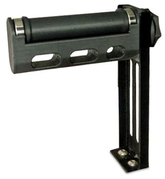
The 3rd part is the original metal bracket that comes with the Ender 5
The 3 parts are all bolted to a plywood base plate.

Rear view of filament roller, load bar & extruder mount location and fixings.
Note load bar spacers to keep reel and reel rollers weight onto left end of load bar only.

Creality Logo

The Logo can be downloaded from here and is simply screwed to the top rail.
To print a 2 colour LOGO in Cura you can pause the printer just as it starts printing the LOGO letters and then change filament colour.
I set a script in Cura to automatically pause the printer at a set layer.
To do this first slice your object.

In the Cura menu select "Extensions" then "Post Processing" and then "Modify G-Code"

In the popup select "Add a script" then "Pause at height"

These are the settings I used

To find the correct layer to pause at drag the layer slider on the right down until the letters start printing.
The layer number will be shown on the slider.

When the printer pauses I have left the extruder hot so the old filament can be pulled out.
Insert the new filament and push it through the hot end until the colour runs true.
Pull back a little bit of filament then start the printer off again.
Adding a Custom Post Processing Modify G-Code Script
To save keep modifying the "Pause at hieght" script each time you can add your own script.
The script is called PauseAtHeight.py just search for it.
I found mine here C:\Program Files\Ultimaker Cura 4.10.0\plugins\PostProcessingPlugin\scripts
or if you update CURA C:\Users\brett\AppData\Roaming\cura\4.11\scripts
Copy it and paste it into your "scripts" folder "Help" "Show Configuration Folder"
I renamed it "PauseAtLayer"
The file was modified to my default settings as follows in Notepad++
Search for the line "PauseAtHeight" and change both occurencies to "PauseAtHeight"
In the "pause at" section I changed the "default_value" to "layer_no"
The "retraction_amount" "default_value" was changed to 4
The "standby_temperature" "default_value" was changed to 230
The "display_text" "default_value" was changed to "Change Filament"
Save changes and re-open Cura now when you go to "Extensions" "Post Processing" Modify GCOGE" "Add a Script" your script should be listed

Once clicked on your default settings defined in the script will be loaded.
All you need to do each time is change the "Pause Layer" setting to suit your print.

Printer Add-Ons
Octoprint
OctoPrint is an open source 3D printer controller application, which provides a web interface for the connected printers.
It displays printers' status and key parameters and allows user to schedule prints and remotely control the printer.
OctoPrint provides a web interface for controlling 3D printers, allowing the user to start a print job by sending G-code to a 3D printer connected via USB.
OctoPrint monitors the status of the print job, as well as the printer itself, including the temperature of the print head (hot end) and the temperature of the bed, if the bed on the printer is heated.
OctoPrint can also show the output of a connected
webcam in order to monitor the state of the print, and can visualize the G-code
in sync with the print job, or asynchronously.
OctoPrint has a plugin
system, allowing users to extend functionality. There are currently over 150
plugins listed in the official plugin repository.
These include advanced timelapse videos that trigger
by layer and position the model and print head properly, 3D design collection
sites such as MyMiniFactory,STL.garden, integrating OctoPrint with Android apps
and Android Wear modules and a Pebble smartwatch.
OctoPrint can run on a
variety of systems, but is commonly run on Raspberry Pi. A distribution called
OctoPi, based on the Raspbian OS for Raspberry Pi, provides a pre-configured
version of OctoPrint along with an mjpeg-streamer support for webcams.
OctoPrint recommends using
the Raspberry Pi 3B, 3B+ or 4B and specifically warns against using the
Raspberry Pi Zero W due to severe performance issues observed.

Raspberry Pi v3 configured as OctoPi

OctoPrint Power & Activity Monitor

Raspberry Pi External Status LEDs
With the OctoPi Raspberry Pi housed under the printer control panel I needed a circuit to show the LEDs next to my Raspberry Pi voltage monitor.
I found this info on https://superkris.tweakblogs.net/blog/14481
I was unable to contact SuperKris to ask permission to use some of his written content as tweakers would not let me register as I have a UK IP address.
The circuit uses a pair of opamps to sense the change in voltage and control a pair of external Power and Activity LEDs.
The opamp input pins are soldered to Raspberry Pi test pads.
Activity LEDs test pad connection on the Raspberry Pi 3 Model B

Power LEDs test pad connection on the Raspberry Pi 3 Model B

The test pad's give about 3.3V when the LED's is off, and down to 2V when the LED is on. We need to translate this to 0V and 5V so we can send it to a LED.
The opamps in the circuit below are used as comparators

.
A comparator can be build with a simple OpAmp. A OpAmp has a positive input and negative input. Putting a voltage on the positive input will raise the output voltage.
Putting a voltage on the negative input wil lower it. A OpAmp (operational amplifier) wil also amplify the input.
You can set is to 0, to 10x, to 1000x, etc. By default the gain is extremely
high. For example 100.000 times or even much higher.
In a comparator we
can use both characteristics to our advantage. If we compare the voltage of the
negative input to our positive input we can calculate the output.
For
example: -5V + 6V = 1V. Simple right? Now if we multiply this by 100.000 we get
a output voltage of 100.000V. Off course this if far from possible, so what
happens in the real world?
The opamp "clips" to the available power supply (minus a small voltage needed by
the OpAmp to work) As a opamp has a positive power supply (Vcc+) and a negative
power supply (Vcc-) the opamp will clip to Vcc+ in this example.
So a
comparator can compare a reference voltage to a measured voltage an tell you
which one is higher.
If you use a positive power supply only(Vcc+) of 5V (Vcc- connected to GND) and you have a 0,001V (1mV) difference between your voltage reference and the measured voltage, the output of the comparator will be either 0V or 5V.
This is great for controlling a LED. The average power output of a opamp is enough to supply enough power to a few LED's
We know the test pad voltages are approx 3,3V with the
LED's off, and 2V with the LED on. If we compare this to 2,65V (the number
between 2 and 3,3) the comparator can easily tell if the LED is on or off.
So we need a reference voltage
(Vref) for the comparator to work with. Actually anything below 3,3V and above
2V will do, but these voltages may vary a little bit. A voltage divider with
resistors is the most simple way to do this.
2 resistors of the same value
connected between 5V (Vcc) and GND will give 2,5V, This is close enough so this
will work fine in most cases.
If 5V however is actually 4,5V the output of the divider will be 2,25. If you use the populair E12 resistor series you can have a 10% error in the resistor value. This can make your Vref drop below 2V.
Therefore I prefer setting the Vref manually with a precision trim potentiometer. I most cases however 2 resistors will work just as good.
Vero Board Layouts

Rear of Vero (Board flipped down from the top)

Octoprint Plugins
For detailed info go here
Control printer environment (Temperature control / Lights / Fans and Filament
Sensor) using Raspberry Pi GPIO
This plugin is intended to control your
printer enclosure using raspberry pi GPIO (At the moment this plugin only
support raspberry pi).
A list of things that you can do:
Add
temperature sensors on your enclosure or near your printer
Add active heaters
on your enclosure and keep the temperature nice and high for large ABS
Use
custom Gcode to control rapsberry pi GPIO
Use custom Gcode to control
neopixel
Use custom Gcode to control enclosure temperature
PWM controlled
outputs
PWM controlled outputs based on temperature sensor
Active cooling
for good PLA printing
Schedule GPIO’s to turn on and off with a fixed period
of time during printing.
Mechanical buttons to pause and resume printer jobs
Mechanical buttons to send GCODE to the printer
Mechanical buttons to control
raspberry pi GPIO
Multiple filament sensors for dual or more extruders
Alarm when enclosure temperature reaches some sort of value
Notifications
using IFTTT when events happen (temperature trigger / print events / etc)
Add
sub-menus on navbar to quick access outputs and temperature sensors
There is
also an API that can be used to interact with the plugin with other software
Octoprint Enclosure Manual Controls


Enclosure Settings
| Button Name | Output Type | Output |
| HOME | Gcode | G28 |
| BED HEAT 60°C | Gcode | M140 S60 ENTER ; change Sxxx for your temperature |
| NOZZLE 240°C | Gcode | M104 S240 T0 ; change Sxxx for your temperature |
| NOZZLE 200°C | Gcode | M104 S200 T0 ; change Sxxx for your temperature |
| STOP | Gcode | M112 |
| COOLING | Gcode | M104 S0; Set Hot-end to 0C (off) |
| M140 S0; Set bed to 0C (off) | ||
| STEPPERS OFF | Gcode | M18 |
| G21 | ||
| G90 | ||
| G4 S5 | ||
| G92 E0 | ||
| FILAMENT LOAD | Gcode | G21 |
| G90 | ||
| G4 S5 | ||
| G92 E0 | ||
| G1 E575 F2000 ; quickly insert the filament untill the hotzone (change Exxx for your length) E525 length for shorter tube | ||
| G92 E0 | ||
| G1 E25 F200 ; slowly insert the filament into the hotzone and extrude a little bit more to prime it (change Exxx for your length) | ||
| G92 E20 | ||
| M400 | ||
| AUTO BED LEVEL | Gcode | G28 |
| G29 | ||
| FILAMENT UNLOAD | Gcode | G21 |
| G90 | ||
| G92 E0 | ||
| G1 E10 F100 ;extrude a little bit slowly to prevent blob forming (change Exxx for your length) | ||
| G92 E0 | ||
| G1 E-650 F2500 ;quickly unload the filament (change E-xxx for your length) E525 length for shorter tube | ||
| G92 E0 | ||
| M400 | ||
| PAUSE | Gcode | M125 |
| FILAMENT RETRACT | Gcode | G21 |
| G90 | ||
| G92 E0 | ||
| G1 E-120 F2000 | ||
| G92 E0 | ||
| M400 | ||
| HOME XYZ | Gcode | G91 ;home with bed lowered for cleaning |
| G0 Z+50 | ||
| G90 | ||
| PURGE | Gcode | G21 |
| G90 | ||
| G4 S1 | ||
| G92 E0 | ||
| G1 E20 F100 ; slowly insert the filament into the hotzone and extrude a little bit more to prime it (change Exxx for your length) | ||
| G92 E20 | ||
| M400 |
Note the OctoPrint SHUTDOWN button does note use the Enclosure plugin but uses the GPIO Shutdown plugin.
GPIO Shutdown is a simple plugin that can shutdown the Raspberry Pi if a switch connected to ground and one of the GPIO pins pressed.
This plugin also turns On a led when Octoprint server is up and running.
Connect a led to one of the GPIO pins and other end to ground, then set the pin number (BCM Mode) in plugin settings in web interface.
OctoPrint Shutdown & Power Buttons
The LED goes Green when OctoPrint is powers up and Red the server is up and running.
Never power down OctoPrint when the LED is Red. Press the Octoprint Shutdown button and wait for the LED to go Green.

GPIO Shutdown Configuration
In web interface, install the plugin and reload if
necessary, then click on GPIO Shutdown, you will have:
Pin Shutdown: Raspberry Pi
GPIO pin (BCM Mode) your shutdown switch is attached to.
Pin Led: Raspberry Pi GPIO pin
your ready-to-run led attached to. This led will turn On when OctoPrint is up
and ready to run/connect.
Denounce Time: When pressing
the shutdown switch, wait for this amount of time to wait for the signal to
stabilize.
My Settings

Looped animation showing Power up, Shutdown & Power off sequence and indications for OctoPrint

Control Connections
| Cable | Button | PCB Connector | GPIO |
| Bl | Stop | Bn | 4 |
| Wh/Bl | Nozzle 200C | Bk | 17 |
| Or | Heat240 | Wh | 27 |
| Wh/Or | Bed 60C | Sl | 22 |
| Gn | Home | Vi | 10 |
| Wh/Gn | HomeXYZ | Bl | 9 |
| Bn | Fellament Unload | Gn | 11 |
| Wh/Bn | Fillament Retract | Yl | 5 |
| Sl | Fillament Load | Or | 6 |
| Wh/Sl | Purge | Bn Rd | 13 |
| Rd | 3.3v via 1K | Rd | |
| Bl | Cooling | 19 | |
| Rd Bl | Pause | 26 | |
| Or | OctoPrint Shutdown | 18 | |
| Rd Or | Auto Bed Level | 23 | |
| Gn | Steppers Off | 24 | |
| Rd Gn | LED | 25 | |
| Bk Or | Gnd | ||
| RdBn | 3.3v | ||
| Filament Sensor | Gnd | ||
| Filament Sensor | 12 |
Raspberry Pi GPIO Pins

Note: the numbering of the GPIO pins is not in numerical order;
GPIO pins 0 and 1 are present on the board (physical pins 27 and 28) but are reserved for advanced use (see below).

Any of the GPIO pins can be designated (in software)
as an input or output pin and used for a wide range of purposes.
Voltages
Two 5V pins and two 3V3 pins are present on the board,
as well as a number of ground pins (0V), which are unconfigurable.
The remaining pins are all general purpose 3V3 pins,
meaning outputs are set to 3V3 and inputs are 3V3-tolerant.
Outputs
A GPIO pin designated as an output pin can be set to
high (3V3) or low (0V).
Inputs
A GPIO pin designated as an input pin can be read as
high (3V3) or low (0V). This is made easier with the use of internal pull-up or
pull-down resistors.
Pins GPIO2 and GPIO3 have fixed pull-up resistors, but
for other pins this can be configured in software.
More
As well as simple input and output devices, the GPIO
pins can be used with a variety of alternative functions, some are available on
all pins, others on specific pins.
PWM (pulse-width modulation)
Software PWM available on all pins
Hardware PWM available on GPIO12, GPIO13, GPIO18,
GPIO19
SPI
SPI0: MOSI (GPIO10); MISO (GPIO9); SCLK (GPIO11); CE0
(GPIO8), CE1 (GPIO7)
SPI1: MOSI (GPIO20); MISO (GPIO19); SCLK (GPIO21); CE0 (GPIO18); CE1 (GPIO17);
CE2 (GPIO16)
I
2C
Data: (GPIO2); Clock (GPIO3)
EEPROM Data: (GPIO0); EEPROM Clock (GPIO1)
Serial
TX (GPIO14); RX (GPIO15)
Fire Shutdown with IOT alerts
The fire shutdown circuit uses a commercial smoke alarm connected to an ESP2866 microcontroller and wireless mains switch.
On detecting smoke the alarm sounds and the printer and fan are immediately shutdown from the mains socket.
A customized alert with picture if required is also sent direct to your mobile phone.
This controller uses Pusingbox to send an instant alert via Push Bullet to my mobile and PCs.
PushingBox is a cloud service that can send notifications based on API calls.
From one request, you can send several notifications like a Push, a Tweet, an Email... All this in real time.
Pushbullet bridges the gap between your phone, tablet, and computer, enabling them to work better together.
From seeing your phone's notifications on your computer, to easily transferring links, files, and more between devices, Pushbullet saves you time by making what used to be difficult or impossible, easy.
Below-Instant alert received on my mobile.
The live image from my 3D printer is from the Octoprint Printoid app.

The Pushbullet alert will also pop up on all your running PCs and laptops.

The fire shutdown control is fitted above the smoke detector.

The detector and controller are mounted on a 3D printed stand that bolts into the Ender 5 v-frame.

The controller uses microphone module connected to an ESP8266.
These are mounted on a Vero Board.

The mains is controlled by a "DEWENWILS" wireless switch and socket.

The wireless switch is modified so it is controlled by the ESP8266
Remove the four screws holding on the rear cover to expose the PCB.
The PCB is held down by 2 screws.

PCB close up.
The On switch is at the top with the Off button at the bottom.
The battery terminals have been de-soldered to be replaced by a 12v feed from the printer.
The relay in the Fire cutoff controller is soldered to the 2 terminal is Yellow marked Com (common) and NO (normally open)
The relay when operated just acts as the Off switch.

Schematic (click for full size image)

The Microphone is de-soldered from the module and inserted into the smoke detector.
Remove the four screws that hold the smoke detector together then drill a small hole for the mic wires.


Microphone wires coming out of the top of the smoke detector and through the mount.
Note fixing bolts extend up into the control box to fix it and the smoke detector to the mount.

Underside view of mount showing how the smoke detector base fixes through the mount using 2 x M3 countersunk bolts.

Vero Board Layouts
Modules in place. The relay and microphone modules are mounted vertically.

Plug in modules removed
Note nuts are smaller than Vero Board holes and do not fix the vero Board in place.
These nuts fix the smoke alarm and controller case to the mount only.
The Vero Board is a friction fit in the controller case.

Rear flipped down

Smoke Alarm software v09 -add alert to confirm detector online on power up

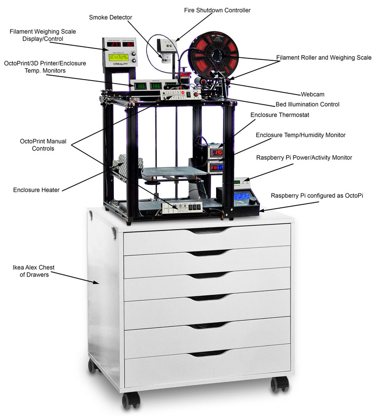
Fillament Scale
This is based on a Nuts & Volts designed filamant scale
I have modified the LCD display slighty and added a 0.56" LED display for Filament Remaining and Filament weight.
The load cell to measure the filament weight is built into a 3D printed reel holder based on 2 seperate designs combined together.

Schematic click for full size version

Vero Board Layout

Vero with NANO in place

Rear of Vero (flipped down)

Fillament Reel Holder and Load Cell
Universal Filament Reel Holder supports reels internally or externaly.
Load cell is attached to the base.

Reel mounted on holder
Large reels will sit on the lower 2 rollers while small reels run on the top roller.
On large reels the top roller prevents reels twisting off the lower rollers when filament is low.

Temperature Panel

The temperature panel contains 3 digital thermometers to monitor the Enclosure, Ender 5 Pro processor and Octoprint (Raspberry Pi).
Available from Amazon they are very cheap and when tested seem to be accurate.

Each thermometer comes with a remote sensor.

The box is printed with a white front panel by printing the white layer first. Letters are printed on inkjet transfer paper and then varnished over.
Enclosure Thermostats
STC 1000
Enclosure Fan Control
This thermostat controls an extractor fan that extracts heat/fumes out of the enclosure. The fan is on an outside wall and the 3D printer enclosure fits around it.
There is a manual override switch fitted to the top of the STC1000 so the fan can be set on manually when printing ABS.


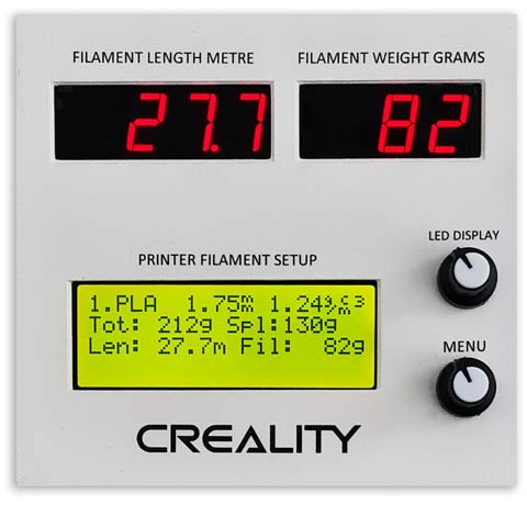
Enclosure Heater & Humidity
STC 3028
This thermostat is used to control a 100W ceramic heater mounted on a length of aluminum extrusion on the side of the printer.

100w 240v ceramic heater.
The heater is surrounded by a guard to prevent touching the hot element and the STC 3028 sensor is mounted within the guard.
A 240v switch isolates the element when not in use.

Heater mounting location


The thermostats are mounted in 3D printed cases and are then fixed to the rear right upright.
Case 3D printer files are here

Thermostats in cases mounted on RH upright

Case 3D printer files are here on Thingverse
Case Top

Case Bottom

Case Front

Original case rear (left) and my designed blank case rear (right) - download here


BLTouch
The updated printer firmware will allow you to set the Z offset, which controls the position that the printer considers to be “0” directly on the print bed. Follow these steps to calibrate the offset:
Auto home the 3D printer.
Place a sheet of paper under the nozzle, then move the Z position (Prepare » Move Axis » Move Z) until you can feel resistance on the paper but you can still move it. Write down the ending value (it may be negative).
Navigate to Control » Motion » Z Offset. Adjust the value by the amount from the previous step (for example, if the recorded value is -.4, adjust the value to be .4 less than the current value).
Under Control, select Store Settings to save the offset. Note that some firmware versions store this on the SD card and not on the printer itself
Power the printer off and back on, then auto home the printer, and verify that the nozzle is positioned correctly.
In the same menu, select Disable Stepper to unlock the motors, and repeat the leveling process at each corner (just like standard leveling).
Move the nozzle to a corner of the bed.
Place your sheet of paper and adjust the leveling knob until you feel some resistance when moving the paper.
Repeat on each corner.
Now that the bed is level, fine tune your Z offset by repeating steps 2-4.
Replace the Gcode command “G28” in your slicer’s starting script with “G28 G29” to run mesh bed leveling before each print.
You are now ready to run a test print! We recommend testing with a model that has a large footprint to make sure the leveling is correct. If you notice that the first layer is too high or too low, you can “live adjust” the Z offset in the Tune menu if you notice that the first layer of your test print is too high or too low. Any changes you make here will persist for future prints as well.