
Section Top Modifications Visual Studio Code Electronic Parts Case Assembly Schematic Vero Board Layouts 3D Printed Parts Operation Downloads
GPS NTP TIME SERVER
Stratum 1 GPS ESP8266 NTP WIFI Time Server
I wanted a reliable time server for some of my NTP clocks as pool.ntp.org would sometimes fail for a day or so and I could never find out why.
I decided to build a GPS NTP Time server and found Cristiano Monteiro design which I could easily modify to suite my requirements.
The 3D files to build this project can also be found on Thingiverse.
Clock Strata
NTP uses a hierarchical, semi-layered system of
time sources. Each level of this hierarchy is termed a stratum and is assigned a
number starting with zero for the reference clock at the top.
A server synchronized to a stratum n server runs at stratum n + 1.
The number represents the distance from the reference clock and is used to prevent cyclical dependencies in the hierarchy.
Stratum is not always an indication of quality or reliability; it is common to find stratum 3 time sources that are higher quality than other stratum 2 time sources.[a] A brief description of strata 0, 1, 2 and 3 is provided below.
Stratum 0
These are high-precision timekeeping
devices such as atomic clocks, GNSS (including GPS) or other radio clocks.
They generate a very accurate pulse per second signal that triggers an interrupt and timestamp on a connected computer.
Stratum 0 devices are also known as reference clocks.
NTP servers cannot advertise themselves as stratum 0.
A stratum field set to 0 in NTP packet indicates an unspecified stratum.
Stratum 1
These are computers whose system time is
synchronized to within a few microseconds of their attached stratum 0 devices.
Attachments can be direct, GPS or DCF77 etc.
Stratum 1 servers may peer with other stratum 1 servers for sanity check and backup. They are also referred to as primary time servers.
Stratum 2
These are computers that are synchronized over
a network to stratum 1 servers.
Often a stratum 2 computer queries several stratum 1 servers.
Stratum 2 computers may also peer with other stratum 2 computers to provide more
stable and robust time for all devices in the peer group.
Stratum 3
These are computers that are synchronized to
stratum 2 servers.
They employ the same algorithms for peering and data sampling as stratum 2, and
can themselves act as servers for stratum 4 computers, and so on.
The upper
limit for stratum is 15; stratum 16 is used to indicate that a device is
unsynchronized.
The NTP algorithms on each computer interact to construct a Bellman-Ford shortest-path spanning tree, to minimize the accumulated round-trip delay to the stratum 1 servers for all the clients
Credits
This project uses an ESP8266 NodeMCU module and GPS receiver to produce a local Stratum 1 WIFI time signal and is housed in a wall mounted 3D printed enclosure.
This circuit is based on a Stratum 1 Time Server designed by Cristiano Monteiro.
See his LinkedIn page here https://www.linkedin.com/pulse/iot-maker-tale-stratum-1-time-server-built-from-scratch-monteiro/
with all source files here https://github.com/Montecri/GPSTimeServer
Cristiano Monteiro based his code on the work of http://w8bh.net/ look under Arduino Projects/Clocks.
Modifications
I have not changed much at all just removed the battery and associated charging circuits.
I have left the WIFI On/Off button even though it is not really needed on my mains powered device.
I have added a Reset button to reset the server in case of errors.
I have also added a miniature PIR to shutdown the OLED display when no one is near the device.
I think the service life of the OLED display is not too long especially for a static display.
The data sheet gives this warning "When displaying images, keep them rolling, and avoid one fixed image displaying more than 30 seconds".
As this device will be on 24/7 the PIR should maximize it's life.
I have included a schematic for my version along with a Vero board layout.
I have designed a 3D Printed case that should be large enough to hold Cristiano's battery version if required.
All 3D printer files are included along with FreeCAD files so you can make modifications to suit.
Visual Studio Code
In order to program the ESP8266 you will need to install Visual Studio Code.
Visual Studio Code is a source-code editor made by Microsoft for Windows, Linux and macOS.
This is used instead of the standard Arduino IDE.
Visual Studio Code in use

Files in Visual Studio Code
Visual Studio Code differs from the Arduino IDE in the location it stores your code files.
As can be seen from the snapshots from Windows Explorer on my PC I have made a folder for the code within My Documents\Arduino\Arduino Sketches\GPSTimeServer-main\
Each version has a folder eg Brett01 , Brett02 etc.
In the folder Brett02 paste the platformio.ini file
Make a new folder in the Brett02 folder called "src".
In the src folder paste the code main.cpp

Parts Required
ESP8266 NodeMCU


PIR HC-SR501 Module
I have used a PIR module to turn off the OLED display when no one is in the room.
The PIR has 2 trimmer resistors for adjusting sensitivity and also length of time the PIR & display stay activated.

I had tried the simple version of the PIR see image below, but had false triggers/noise from the ESP8266.

I kept the small diffuser from the simple PIR and replace the larger diffuser with it.


The large diffuser can be used if required and I have made a front panel to fit the larger diffuser if required.

GPS Module
GY-NEO6MV2 NEO-6M GPS Module with PPS
In order to capture the GPS signals, a GPS chip is needed in the form of a
module. Make sure your GPS module has PPS “Pulse Per Second” output.
PPS
is a squared wave electrical signal with a less than one-second width but with a
precise 1 Hz frequency. 1.000 pulses per second.
This signal is of vital
importance to keep a time server synchronized with the atomic source, by
synchronizing top of the second shift with PPS input.


GPS Antenna
Waterproof Active GPS Navigation Antenna with 28dB gain.
This antenna allows me to fix it externally to get a good reception.

Make sure you antenna comes with a SMA to IPEX converter cable.

RTC
The RTC stores the time and date in battery backed memory when power is removed.


Modification of DS3231 AT24C32 I2C Precision Real Time Clock Module
There has been a possible fire risk associated with the circuit design of these modules when used with rechargeable bateries.
I use a non rechargeable battery and remove charge resistor R5 see details below.

My clock uses a DS3231 AT24C32 I2C Precision Real Time Clock Module instead of a DS1307.
The module comes supplied with a Lithium-Ion rechargeable battery see diagram above. I use a non rechargeable battery so have removed resistor R5
from the module as below.

Location of R5 on the DS3231 module.

Charging Resistor R5 removed.

0.96" OLED Display
This clock uses a .96 inch 128x64 I2C SSD1306 OLED display.
The display uses the same 2 wire bus as the RTC.

About OLEDs
OLED (Organic Light Emitting Diodes) is a flat light emitting technology, made by placing a series of organic thin films between two conductors.
When electrical current is applied, a bright light is emitted.
OLEDs are emissive displays that do not require a backlight and so are thinner and more efficient than LCD displays (which do require a white backlight).
Rear of OLED

To keep the life of this OLED display to it max I have added a PIR to turn the OLED display off when no one is in the room.
The Case
The case is made up from 3 separate 3D printed parts.
Below back box and plate for the rear of the front box.

The front case is fixed to the rear box with 4 off 3mm self tapping screws.
![]()
The case labeled using inkjet transfer paper.
See details on my DCF77 Analyzer clock page.

Case Assembly

Starting from the rear box.

Before assembling the Server mark fixing screw positions on the wall and temporarily fix in place. The screws should be tight enough to allow the box to be slid in place once the server has been assembled.
Mark the position of the cable hole on the wall (if hidden wiring is used).

Slid the rear box off the mounting screws.
Glue (hot melt glue works well) the top Vero Board clip in place in the bottom of the box against the top side with rebate facing down.

Slide in the assembled Vero Board including the Vero Board Spacer into the rebate of the glued in strip.
The Vero Board Spacer is screwed to the rear of the Vero Board with M2 self tappers.
This allows space for the solder joints and screw heads holding the case to the wall.
I wire short 5v power and GPS coax tails at this stage and feed then through the cable hole.

Insert the 3 Vero Board Clips onto the Vero Board ensuring the rebates face down & in towards the Vero Board.

Lay the rear front panel over the rear box lining up the 4 inner corner holes and fix the 3 Vero Board clips to the rear front panel using 3 off M3 self tappers.

If disassembling in the future these 3 screws can be left in place.
Vero Board mounting clips fixed to the rear front panel.

This is a view from below with the rear box removed showing how the the 4 Vero Board clips hold the board in place.
Note the black Vero Board spacer in place. this holds the Vero board off the wall fixing screws.

Using 4 off M3 self tappers fix the rear front panel to the rear box.

This picture shows the switch panel, OLED, indicator LEDs and the PIR are located over the Vero Board below.
These items are of course fixed to the front panel.

This picture shows the switch panel, OLED, indicator LEDs and the PIR are located on the rear of the front cover.
They are all held in place with hot melt glue.

Plug in all wires from the Vero Board to the front panel components.
The front cover in place with all components fitted is then placed over the rear box locating over the rear front cover plate.
Using 4 off M4 self tappers fix the front cover in place through the four corner holes in the rear front cover plate.

Connect the 5v and GPS tail connectors to the wiring coming out of the hole in the wall and then slide the server in place over the fixing screws.
I have used an external GPS aerial fitted on the roof above my office with the time server located high up near the ceiling.

Case Rear View Sections
Rear view of completed case

With the rear box removed the 4 rebated clips that hold the Vero Board to the base of the rear box can be seen.
Note the black Vero Board spacer fixed to the rear of the Vero Board.
Vero Board and spacer removed showing the Vero Board clips and rebates that fit over the board.

Vero Board clips removed to so the rear front cover plate fixed to the front cover.

Rear front cover plate removed showing locations of the GPS, OLED, Swich board and LEDs on the rear of the front panel.

Front panel rear showing holes for he GPS, OLED, Swich board and LEDs.

Schematic
Click to view full size version

ESP8266NODEMCU Pin Outs

Vero board Layouts
Click to enlarge


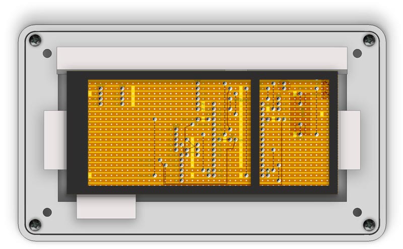
Completed Vero Board with spacer below

Vero Board Layout Control Switches

Vero Board mounted inside the rear box.
The screws hold the Vero Board to the Vero spacer not the case.
The Vero Board is held in place by 3D printed clips.
The first seen in the pic below is hot melt glued to the rear case and has a rebate to hold the Vero Board.

3D printed Vero Board clip showing rebate that holds one side of the Ver Board in place.

There are 3 other Vero Board clips also so with rebates that fix to the rear front panel cover with M3 self tappers.
Vero Board clips showing Vero Board rebate.

Rear front panel cover with Vero Board Clips screwed in place. The rear panel cover is screwed to the rear box with 4x M3 self tappers.
The four outside corner holes are used to fix the rear box assembly to the front cover.

3D Printed Parts
There are 2 front case type one below with the small PIR diffuser cutout
Front case small PIR Diffuser (taken from a smaller PIR module)

Rear view showing rebate for the OLED screen.

Front case large PIR diffuser. This is the standard diffuser

Rear view showing rebate for the OLED screen.

The rear front plate fixes first to the rear box with M3 self tapers using the inner four corners holes then to the front box recess with M3 self tappers using the four outer corner holes.
The other 3 holes fix 3 of the Vero Board clips to this panel.

Rear Case

GPS Spacer
This simply fits under the end of the GPS Board to support if off the Vero board.
Fixed to the Vero Board with hot melt glue.
The GPS module can be fixed to the spacer with self tappers if required.
![]()
RTC Spacer
Due to the way I have spaced the RTC Module on the Vero Board there is a slight overlap of the RTC and the GPS module.
This spacer keeps the RTC Module off the GPS module.
Fixed to the Vero Board with hot melt glue.

Vero Board Support/Spacer
This part is fixed to the bottom of the Vero Board with M2 self tappers through the top of the Vero Board.
It keeps the soldered joints of the bottom of the box. allows space for the fixing screw heads and supports the Vero Board.

Vero Board Clip
This part has a rebate in the bottom to fit over the Vero Board with spacer fitted. It is hot melt glued in place.
The Vero Board with spacer slides under the rebate ready to be locked in place with the other 3 spacers.
Vero Board Clip
This part has a rebate in the bottom to fit over the Vero Board with spacer fitted.
Once 3 of these are fixed to the rear front plate with M3 self tappers along with the rear vero Board clip they will lock the Vero Board in place.
3 off required.
Below the 3 clips shown fixed to the rear front cover plates with self tappers

Below bottom view showing the Vero Board held in the 3 clips plus the rear clip
Cable Tie Fixing
Hot melt glued to the back of the front case provides support to tie the wires from the modules.
This helps keep strain off the connections.

Vero Switch Spacer
Fits over the switches on the switch panel to space the switches off the front panel to ensure correct protrusion of the switch covers through the front case.
![]()
Operation
PIR

The PIR can be adjusted for sensitivity and time on after trigger.
Controls
Pressing the Red Reset button momentarily resets the ESP8266 and reloads the code.
Pressing the Yellow WIFI Button momentarily turns the WIFI sever off.
Pressing again turns it on.
Indicators
Yellow LED illuminated indicates that the WIFI server is On.
Red LED shows the PPS pulse and once synchronized to satellites it will flash once per second.
Green LED illuminates when the signal is locked.
OLED Display
The OLED display shows the number of satellites connected -line 1 left
Resolution line 1 right
Date line 2 and UTC time line 3.
Setting up the Time Server
The server will require a name and a password if you do not want the server open.
This is done in line 29 & 30 in the code.
#define APSSID "TimeServer" // Default AP
SSID
#define APPSK "password" // Default password
The current sever name is TimeServer with a Password of password.
Power up the server and you should get a the WIFI LED illuminating after a few seconds.
After a short time the Green lock LED should light followed by the Red PPS LED flashing every second.
If you open your phone WIFI connection you should be able to see the server listed by the name you set above.
.

Connect to the server by logging in with your phone using your password set in code
Once connected enter the IP address in your phone browser 192.168.4.1
You should get the message "You are connected"

You should now be able to test the server by connecting your NTP clocks using the ssid & password set above.
Front Panel Text Layout
I have included a front panel layout so it can be modified to suit.
Zip includes TurboCAD, AutoCad and PNG files.
Note print without the boxes and circles but leave the cross hairs in place for positioning the inkjet transfer.
I leave the outside box as well as a trimming guide i.e. I cut the transfer inside this line.


3D Parts Download
Includes stl and FreeCAD files
Code Download for Visual Studio Code
Updated 10/08/2022 bug where wrong day was transmitted .

Thanks to Mitch Markin for the bug fix.
I have the time server working on a breadboard right now synching two ESP8266-based clocks I made a couple of years ago. It's running well, but there was a bug in Cristiano's code that made it send the wrong date.
The bug originated in the code that Cristiano got from an Arduino forum and he wasn't aware of it until I mentioned it yesterday. Since you based your code on Cristiano's, I see the bug is in your code too.
It's an easy bug to overlook if your clocks don't show the date. The time comes in from GPS OK and it gets displayed properly on the OLED screen.
The clocks sync to the server and show the proper time but they showed dates that were one day fast.
The problem is in the numberOfSecondsSince1900Epoch() function. It starts counting the days by saying uint16_t days = d; where d is the parameter passed to the function that specifies the current date. So that counts the current day as a full day.
Then later it also adds the current day's hours, minutes, and seconds, so the total seconds calculated is one day too big.
It's easy to fix. Just change the uint16_t days = d; statement to say uint16_t days = d - 1; That way it won't count the current day until it adds its hours, minutes, and seconds.
I let Cristiano know and he fixed the code posted on his Github site about the project.
I also tested the function by running a bunch of dates through it. all the way to March 2028, to see if it deals with the leap years properly. All the NTP timestamps it calculated were good.