

Section Top Credits Construction Veroboard Layouts Schematic Wood Vault Construction Combination Lock 3D Part Location 3D Part List 3D Part Download Arduino Code Euro Modification
COIN COUNTING PIGGY BANK
A 3D Printed Arduino automatic coin counting moneybox and educational toy for children.
|
|
|
NEW Euro currency overlay added.
Designed for children to hopefully get them interested in saving money and also learn the basics of maths.
Can also be used to reward your child when they have been good instead of a star chart. Your child can see their money grow until they can afford a treat.
Coins are placed on the slide and fed into the money box by gravity.
Coins drop into individual slots and counted by an optical sensor before dropping into the safe which is secured by a working 3D printed combination lock.
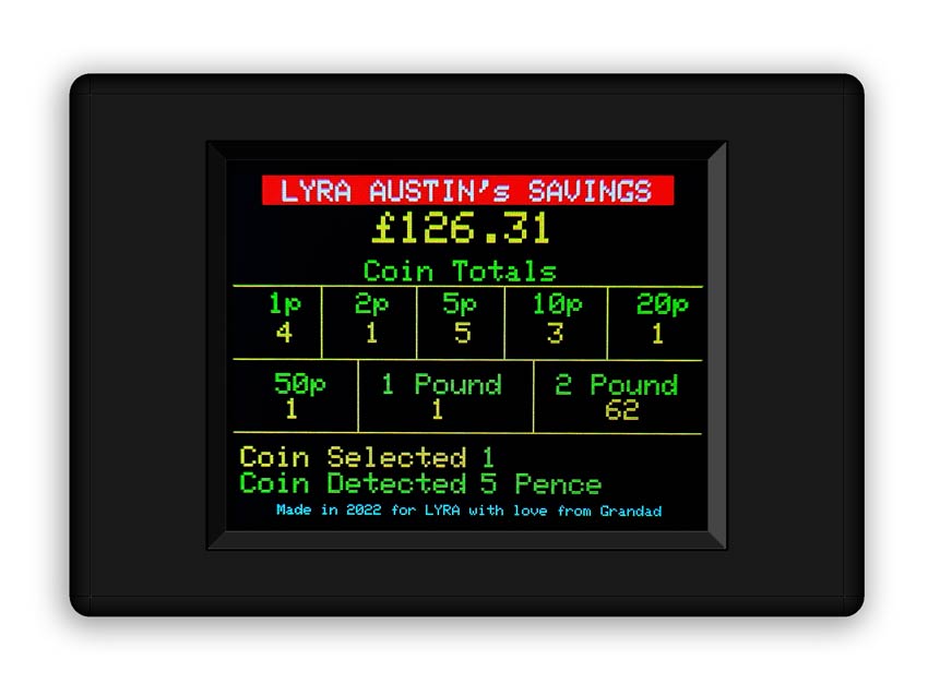
An Arduino Nano counts the coins and displays them on a TFT display showing total savings and how many coins of each value has been saved.
All values are stored on EEPROM and remembered on power up.
Coins can be added and subtracted from the totals using buttons on the control panel.
The Perspex safe door is secured by a fully working 3D printed combination lock.

Below 3D printed combination lock

Video
This project uses an Arduino Nano.

The Arduino Nano and Vero board are mounted in the box below the counting section of the machine.
The rear view below shows the row of optical sensors positioned below each coin slot.

A TFT display mounted above the coin slide shows total coin value and individual numbers of coins in the safe.
It also indicates the last coin detected as well the coin to be added or subtracted from the safe.
Control Panel
A small control panel is fitted in place of the old 7 segment LED display.
The panel has a rotary control to select a coin value, a recessed RESET button for zeroing the display and coin count , a PLUS button for adding coins and a MINUS button for subtracting coins.

Instructions
Resetting the display
Turn the rotary control until the "Coin Selected" on the display shows 0.
Press the recessed "RESET" button. The display will show "ZERO COINS +YES -NO.
Pressing "MINUS" will cancel the reset and the display will show "CANCELLED"

Pressing "PLUS" will show "RESETTING" on the display and the coins values will zero one by one. Finally the total will be zeroed.

Adding & Subtracting Coins
Use the rotary control select the coin to add or subtract. This will be shown as "Coin Selected" on the display.
Pressing "PLUS" adds a coin and "MINUS" subtracts a coin from the coin totals. The total display amount will change accordingly.
Example adding 10p coins

Example subtracting 10p coins

Credits
Coin Sorting & Counting
I have used a modified Coin Sorting & Counting machine from DIY Machines

The following changes have been made
Removed the coin tray so coins drop into the moneybox/safe. Replaced with boxes for Vero board and Arduino Nano.
Removed the LED display and added a TFT display with individual coin count.
Added an additional coin slide.
Added coin labels to the front of the counter.
Added a shield to the front of the £2 slot to stop false triggering of the £2 sensor.
Combination Lock
I have used a modified Combination Lock by Vladislav Trigubovich full details on Thingiverse

Added a case so the lock can be mounted on a plate (Perspex in my case).
The case has a cutout to be covered in a Perspex sheet so the mech can be viewed if required.
The case keeps the coins out of the lock parts. The
case is fixed to the lock with M2 self tappers.
Added a larger knob that can
be rotated to change the combination ( a limited amount) along with changing the
position of the bolts on the code wheels.
The knob overlaps the
printed letters so no precise cutting is required for a neat finish.
Also included a pointer and
mount - print these small files at fine setting 0.12. Simply superglue together
and in place on your panel.
Added a combination wheel
brake to prevent the other combination wheels turning when rotating another
wheel. This replaces 1 of the 4 part no 7s.
Construction
The circuit is built onto Vero Board
The Vero board sits on a spacer on the base of of left hand sloping box under the coin counting machine highlighted below.

The Vero board sits on a 3D printed spacer on the base of the sloping box.

The Nano Mini USB connector faces the rear of the box.
Power is provided by a MINI USB to power adaptor and is plugged in via a hole in the rear of the sloping box.

When programing the Nano this lead is removed and a Mini USB from your PC is connected.
Optical Sensor
The sensor is a TCRT5000 and I have used a prebuilt module.
When a coin slides past, the signal intensity received by infrared reflective sensor increases and the indicator LED on board turns green and D0 goes low.
When the coin has passed, the intensity decreases (the section of channel below the detector is black) and the LED turns off and D0 goes high.
Sensitivity can be adjusted using the preset resistor on top of the module.
Module Specs
Supply Voltage: 3.3V~5V
Detect distance: 1mm-15mm
Digital Outputs HIGH when objects detected
TCRT5000 Modules


Mounting
The Optical sensors modules mount below the slide with the sensors facing into the coin channels.
The sensor modules are fixed in place with M2 self tappers.

The £2 coin sensor far left above fits in its own mount and is pre wired before fixing in place.
Below £2 coin sensor mount front view.
The sensor module fits in the rear with the sensor protruding into the cutout.

Completed wiring loom from the Optical modules.
The loom has 8 wires 1 from each module output plus a 0v and 5v that is common to all modules.

TFT Module
The 2.2" LCD in the TFT01 is a IL19341 and has a 240 * 320 resolution.


Pins
§ SDO: Serial clock output
§ LED: 3.4V Power Supply pin
§ SCL: Serial clock input
§ SDA / SDI: Serial data input
§ DC: Data / Command selection
§ RST: Reset, Low level active
§ CS: Chip Selection, Low level active
§ GND: Ground
|
A level converter is used between the Arduino and some of the TFT display pins as they require 3.3v. |
Level Converter

This bi-directional logic level converter is a small device that safely steps down 5V signals to 3.3V AND steps up 3.3V to 5V at the same time.
The board needs to be
powered from the two voltages sources (high voltage and low voltage) that your
system is using.
High voltage (5V for example) to the ‘HV’ pin, low voltage (3.3V for example) to ‘LV’, and ground from the system to the ‘GND’ pin.
3.3V Regulator Module
This module converts the 5v input into a 3v output for the logic level converter.

Vero Board Layouts
Click boards for larger versions
Layout with modules in place

Layout with modules removed

Layout showing solder side

Schematic
The power is provided by the USB in on the NANO via a 5v regulated supply.
The level converter shifts levels from 5v to 3.3v for use on the TFT inputs.
Click schematic for full size version.

Timber Vault
The vault is a simple timber open fronted box made from scrap timber. I used 18mm Pine shelving board as it's strip construction makes it quite stable.
The timber parts are simply nailed and glued together around the back board timber.
A slot is cut into the top timber board to allow the coins to pass through.
A 3D printed liner covers any uneven edges of this slot.

A slot is cut into the top timber board to allow the coins to pass through.
A 3D printed liner covers any uneven edges of this slot.
The slot is 35mm deep by 273mm wide

Location of coin slot.

The box comprises 5 parts all from 18mm timber.
1 off Back board timber 150mm x 300mm

2 off Side Timber 130mm x 185mm

2 off Top and Bottom Timber 130mm 337mm

4 off 12mm x 6mm timber strips form a rebate for the Perspex. These are fixed in place with M2 screws with the rebate set to the depth of your Perspex sheet.
Below timber strips hi-lighted in green form a rebate for the Perspex door.

To keep the coins from falling out of the vault when the door is open a sloping base is inserted into the vault.
A wooden batten tray support 7mm x 20mm (with a 3mm angled cut at the front end) is placed in the bottom of the vault against the front rebate strip.
Below wooden tray support hi-lighted in blue.

A cut 5mm bit of ply 93mm x 30mm is then laid on top of this batten resting on the bottom of the vault at the rear.
Below location of wooden tray hi-lighted in yellow.
3D printed angled plastic trim is then fixed to the front with M2 screws. Green baize is then added to the sloping tray up to the trim to allow money to slide past the trim when removing it.

Below 3D printed angled plastic trim is fixed to the front of the slop with M2 screws. The trim is printed in CURA x2 with 1 copy being mirrored horizontally.

Perspex Door & Hinges
The hinges are Cabinet Door Self Closing Overlay type.


The Pespex sheet is fixed to the hinges with M3 nuts and bolts.
The perspex is protected with 3D printed hinge support front and rear as well as 3D printed washers.
Hinge Mounting
Front of hinge showing front bolt washers and front hinge washer

Hinge Washers Front & Rear
The rear mounting surface of the hinges has a raised area that will damage the Perspex sheet even with a flat washer over it.
I have added a cutout to the rear washer to accommodate the raised area.

Make sure the rear hinge washers with the cutout are fitted on the rear of the hinge as shown.

Hinge opened to show rear bolt washer and hinge between front and back washers.

I have used 5mm Perspex sheet for the door.

The door is hinged on the right side.
A door catch if bolted to the left side of the vault and holds the door shut when the combination bolt lever is operated.

This is bolted form the outside with M3 bolts or you could secure from the inside with screws.

Holes are drilled in the Perspex for the Combination wheel and Lock lever spigots as well as the M3 mounting bolts from the lock mount case.

To line the slot cut into the top of the vault a plastic trim half is printed x2.

The 2 halves combined form the liner for the slot.
Just clip or glue in place.

The slot liner location on the top of the vault.

To stop coins flying past the coin slot a slot guard is fitted in front of the slot.
Printed in 2 halves (mirror the part in CURA) to get an oppersite.

Completed slot guard.

The slot guard is fixed by 2x M2 screws through the lip of each half into the wood top.

Slot Guard in place fixed with M2 screws.

Combination Lock Construction
The combination lock can be downloaded from Thingiverse.
You will need to print 3 off part-7 and not 4 as my FeltPad support replaces one of these.
I have added a larger Rotary Knob and a letter ring that can be rotated to allow limited changing of the combination along with changing the position of the bolts on the code wheels.
Download these parts from the download section of this site.

Location of new parts on the lock knob.

I have also added a combination wheel brake to prevent the other combination wheels turning when rotating another wheel. This replaces 1 of the 4 part no 7s.
Just stick a bit of felt or draught excluder to this and adjust to give a bit of friction on the combination wheels.

Location of the felt pad holder

To mount the combination lock to the Perspex door and to keep coins from falling into the lock I have designed a case to fit over the lock.

There is an observation hole in the top of the case so you can see the combination wheels through the safe door if the lock malfunctions.
This needs a piece of clear Perspex glued to the top.
The case is fixed to the lock with M2 screws and is fixed to the Perspex door with M3 nuts and bolts.
Below the case printed in clear PLA fixed to the lock. The M3 fixing bolts can be seen holding the case to the Perspex door.
Note I have fitted a small 3D printed knob to one of the bolts to aid opening the door.

Combination Lock Instructions
The combination lock is based on a real lock but only has 3 combinations and only has a limited range of combination settings.
The combination can be changed by rotating the letters around the combination wheel knob and sticking it in place and the hex bolts can be moved to a different location on the three wheels (part 5 and part 3).
The lock below is shown in it's locked position with the bolt forward locking the door shut and the opening lever is locked in place.

To unlock the safe the combination has to be entered in this case K TU NO.
Step 1
Turn the combination knob anti clockwise one full turn.

Step 2
Turn the combination knob anti clockwise until the pointer is on K.

Step 3
Turn the combination knob clockwise one full turn.

Step 4
Now turn the combination knob clockwise until the pointer is midway between the T and the U.

Step 5
For the last combination the knob is just rotated anti clockwise to midway between the N and the O.

Step 6
With the combination inserted correctly the opening lever is now free to move.
Rotating the opening lever anti clockwise retracts the bolt and the safe door can be opened.

Note if you over turn the lock when turning to a letter in any of the above steps the code will need to entered from the start again e.g. start by turn anti clockwise one full turn.
Video showing how the combination mechanism works on a wooden version of this lock.
3D Printed Parts
My additional parts for DIY Machines coin counter
Note the original main body was too large for my printer base so I split it into two parts.
Part Locations front - click to view large image

Part Locations rear - click to view large image

Part Locations Vault - click to view large image

3D Printed Part List
The parts list lists the name of the part, part file name , description and image of each part.
Coin Counter Main Body
project_734_cad_file_4749214
This is the main coin counter body and can be printed in one go if your 3D printer can handle the size.
If not use the 2 halves below.

Coin Counter Main Body Left Half
RightMeshMixer
The main counter body is too big for my 3D printer bed so I have split it into 2 parts.
This is the left hand side of the coin counter body.

Coin Counter Main Body Right Half
LeftMeshMixer
This is the right hand side of the coin counter body.
The 2 parts are glued together.

Vero board housing
CoinTrayleft
Screwed to the coin counter above and to the coin tray right below with M2 screws.
The Vero board is housed in this box.

Vero Board Spacer
VeroSpacer01
Spaces the Vero board from the base.
Fixed with M2 screws through the Vero board and into the base below.
![]()
Vero board housing base
CoinTrayLeftBase
Base for Vero board housing. Fixed with M2 screws through the Vero board housing into the tangs of the base.

Coin counter base right
CoinTrayRight01
Fits below the coin counter and next to the Vero board housing.
Screwed to the coin counter above and to the base with M2 screws.

Base cover
CoinTrayRight02
Base for coin counter base above. Fixed with M2 screws through the coin counter base into the tangs of the base.

Sensor Clamp

This clamp hold the £2 coin sensor in place as there is no acces to the sensor to fit a screw as per the other sensors.

£2 coin sensor mount
After the £2 coin sensor is fixed into the mount and pre wired it is then glued into the right side of the counter body.
2poundcoinmount
£2 coin sensor cover
2poundcover
This cover stops false triggers from the £2 sensor & is fixed to the lower edge of the £2 cover mount below.

£2 cover mount
2poundback
Fixed at it's right hand end to the £2 coin sensor mount this provides support for the £2 coin sensor cover and £2 coin label.

£2 Label
NamePlateFusion02farRight
This is the label for the £2 coin slot and is glued to the £2 cover mount above.

Coin Counter Fixing bracket
BracketFixinhSorter
2 of these brackets are fitted at either end of the coin counter a M2 screw fixes it to the coin counter and 2 x M3 screws fix it to the top of the vault.

Control Panel
ControlPanel01
Mounted to the coin counter in place of the 7 segment display by 4x M2 screws

Control Panel Label Holder
ControlPanelLableSloped
Printed white and holds the label for the control panel buttons.

Control panel button spacer
ButtonSpacer3w01
This is a spacer for the 3 PCB buttons on the control panel.
![]()
Coin ramp
CoinRampE
This ramp adds a bit more speed to allow the coins to slide a bit further.
The 2p coin being light/long travel distance is the one to test.
The coin ramp is fixed to the coin ramp bracket below with 2x M2 screws.

Coin Ramp Bracket
CoinRampBracket02
Bracket for coin ramp above.
This bracket fixes to the coin counter with 3 M2 screws and to the Coin ramp above with 2 x M2 screws.

Coin Deflector
DeflectorCoin
2 of these are required fixed side by side with 2x M2 screws each to the top wooden rebate strip in the vault.

Door Catch
doorcatch
Bolted to the inside of the vault with M3 bolts has a recess to catch the bolt from the lock when operated.
FrontAngledStrip
Covers the wooden batten tray support 2 of these are required.
Fixed to the wooden batten tray support with 2x M2 screws each.
Washer 10m x 2mm with M3.5 hole
Washer10mmx3_5mmx2mm
12 of these are required 6 for each hinge.

Hinge Support
HingeSupport2mm
Spreads the load over the top of the hinge

Hinge Spacer
HingeSupportCropRear1mm
Provides a spacer over the raised area on the back of the hinge to protect the Perspex.

Coin Slot Labels Left
NamePlateFusion02left
Labels for the coin slots. Glued to the Coin counter body.

Coin Slot Labels Right
NamePlateFusion02Right
Labels for the coin slots. Glued to the Coin counter body.

TFT Bezel
TFTBezel02
Housing for the TFT Screen

TFTBezelRearCover

TFT Bracket
TFT_Bracket
Fixes the TFT Bezel via the rear cover to the coin counter body with 6x M2 screws.

TFT Mount Right
TFT_MountSpacerRight
Glued to the TFT bezel & screwed through the TFT screen spaces the TFT from the bezel.
![]()
TFT Mount Left
TFT_MountSpacerLeft
2 of these required. Glued to the TFT bezel & screwed through the TFT screen spaces the TFT from the bezel.
![]()
Pointer
Pointer
Glued to the pointer base below

Pointer Base
PointerBase
Glued to the pointer above and the Perspex door over the rotary knob of the combination lock to indicate the letter selected.

Lock Case/Cover
LockCover
Provides a cover and mount for the combination lock.
Fixed to the lock with 4 x M2 screws and perspex door with 4 x M3 nuts & bolts
Felt Pad Holder
FelpPadSupport
Combination wheel brake to prevent the other combination wheels turning when rotating another wheel. This replaces 1 of the 4 part no 7s.
Just stick a bit of felt or draught excluder to this and adjust to give a bit of friction on the combination wheels.

3D Parts Download
Where parts are my design FreeCAD files are included
Combination Lock

Coin Counter & Safe Files
Arduino Code
EURO Currency Modification
There have been a number of requests on the original site for a Euro version of the counter.
I have added it in the form of an overlay that is fixed to the original counter.
I have also modified the code to match.

Euro and Pound Coin Dimensions
Euro coins sorted in order of diameter small to large compared to Pound coins sorted small to large.
| Number | Euro Coin | Diameter mm | Coin Slot mm | UK Coin | UK Diameter mm |
| 8 | 1 cent | 16.25 | 17.25 | 5p | 18 |
| 7 | 2 cent | 18.75 | 19.5 | 1p | 20.3 |
| 5 | 10 cent | 19.75 | 20.45 | 20p | 21.4 |
| 6 | 5 cent | 21.25 | 22.25 | £1 | 22.5 |
| 4 | 20 cent | 22.25 | 22.75 | 10p | 24.5 |
| 2 | € 1 | 23.25 | 24 | 2p | 25.9 |
| 3 | 50 cent | 24.25 | 24.75 | 50p | 27.3 |
| 1 | € 2 | 25.75 | 26.75 | £2 | 28.4 |
This gave me the locations of each Euro on the coin sorter.
As no Euro coins was bigger than it's corresponding Pound coin in it's slot the simple overlay would work OK.
I used these dimensions for my Euro overlay.

Euro Overlay
The simple overlay covers over the existing slots and is fixed to the sorter with glue.

Euro overlay Extension
An overlay extension was required as my printer bed is too small to print the full overlay.

Coin Ramp Bracket Slotted
I modified the original Coin Ramp bracket by adding slots so the attached coin ramp can be adjusted just above the overlay.

Coin Slot Labels
The coin slot lables have been changed to Euros/ Cents and the coin order has also changed.


Euro Modification Part Location

Euro Currency Code
The TFT display has been modified to display Euros.

Code included in the zip below.
Euro Currency 3D Parts
Parts included in CURA and FreeCAD format in the zip file below.